MV2F CMVS Build

kuze

Sultan of Slugs
10 Year Member
Joined
Apr 20, 2013
Posts
2,557
Forgive me if this is in the wrong sub-forum, I am still a bit new to this forum after all!

I just purchased an MV2F from a member here and am planning my first CMVS build. I'm going to use Xian Xi's two slot guide from JNX as a reference. I have no need for composite or component video, so I'm going to pull straight raw RGB from the board to feed to my XRGB Mini.

My plan is to use the following 8-pin DIN connector for the video/audio:
http://www.digikey.com/product-detail/en/SD-80SN/CP-1280-ND/97027

I'd like to output stereo sound rather than the mono sound that the AES outputs, so my plan is to use the unused pin 7 for the additional sound line. pin 3 will be sync and will end up at the scart pin where composite video usually leads.

I modified eviltim's pinout image to show my plan (gave credit to the original page, but if for some reason it's a problem that I used his image, I'll be happy to take it down):
http://i.imgur.com/qyGuxFT.png

Does anyone see any problems with this diagram? I'm concerned that the JNX image shows pin 7 as being used for sync, and pin 3 for composite video. Should I switch pin 3 and 7 in the diagram?

I also plan to use the following rocker switch, power barrel connector and power supply to provide 5v to the board:

rocker switch: http://www.digikey.com/product-detail/en/1-1571076-0/450-1810-ND/529580

power connector: http://www.digikey.com/product-detail/en/PJ-005A/CP-5-ND/165838

power adapter: http://www.digikey.com/product-detail/en/EPS050100-P5N/T1132-P5N-ND/2361003

Do you guys think that the power adapter I linked would provide sufficient power to the board?

I plan to use the onboard joystick ports on the MV2F, so that covers gamepads. Any thoughts or insight that you all could provide would be highly appreciated, as I'm completely new to this!

Thanks in advance :)
 

Fortune

Zero's Secretary
Joined
Jun 30, 2012
Posts
151
I can't personally give to much of a comment on the RGB+Stereo pinout that you are wanting to use.

That rocker switch should be more than sufficient.

The power adapter is a little too weak for an MV2F. It's only rated for 1A at 5V. It's great that it's a switching power adapter, but you will need a bit more amperage out of it. I think Xian Xi mentioned that this particular board tends to pull about 1.7A or so, so I would give it a bit of headroom. 2-3A 5V switching power supply would probably be great. I've gone with 3A for my own builds just to allow room to add any bits I might want.

Whatever power connector you get will be completely reliant on whatever power supply is ultimately selected.
 

kuze

Sultan of Slugs
10 Year Member
Joined
Apr 20, 2013
Posts
2,557
I can't personally give to much of a comment on the RGB+Stereo pinout that you are wanting to use.

That rocker switch should be more than sufficient.

The power adapter is a little too weak for an MV2F. It's only rated for 1A at 5V. It's great that it's a switching power adapter, but you will need a bit more amperage out of it. I think Xian Xi mentioned that this particular board tends to pull about 1.7A or so, so I would give it a bit of headroom. 2-3A 5V switching power supply would probably be great. I've gone with 3A for my own builds just to allow room to add any bits I might want.

Whatever power connector you get will be completely reliant on whatever power supply is ultimately selected.

Very helpful information! Thanks, Fortune. I picked out a different power supply that's rated at 3A 5V switching:

http://www.digikey.com/product-detail/en/WSU050-3000/237-1387-ND/3094913

Since the power connector I had listed was only rated for 2A, I found another that has a current rating of 5A:

http://www.digikey.com/product-detail/en/PJ-065A/CP-065A-ND/2627223

That should be a good pairing then, right? If anyone has some thoughts on the video scenario I described, I'd be happy to hear them :)
 

skate323k137

Professional College Dropout
10 Year Member
Joined
Jan 7, 2013
Posts
4,224
Pulling RGB from the board should be OK, you may need resistors to tone it down a bit depending on where you pull from. Maybe 220 ohm on R G and B. I'm sure Xian Xi can offer better advice for that.
 

Xian Xi

JammaNationX,
15 Year Member
Joined
Dec 1, 2005
Posts
27,750
For resistors on the RGB lines, it would be a better choice to have them in the cable rather than on the board.
 

xsq

Thou Shalt Not, Question Rot.,
Joined
Jan 17, 2013
Posts
7,414
Oh, I know this isn't what you asked for, but if you can avoid it, don't solder directly to the fingers on the JAMMA edge, use a plug. Keeps the board as "authentic" as possible, won't look any less elegant, and you still have the option to use it in a cab if you want to in the future.
 

kuze

Sultan of Slugs
10 Year Member
Joined
Apr 20, 2013
Posts
2,557
Pulling RGB from the board should be OK, you may need resistors to tone it down a bit depending on where you pull from. Maybe 220 ohm on R G and B. I'm sure Xian Xi can offer better advice for that.

Thanks, Yeah I was planning on using 150 ohm resistors, per Xian Xi's 2 slot CMVS guide.

For resistors on the RGB lines, it would be a better choice to have them in the cable rather than on the board.

I might put them in the cable, any reasoning on why this would be better? I was planning on attaching the resistors to the solder side pins of the 8-pin DIN connector.

Oh, I know this isn't what you asked for, but if you can avoid it, don't solder directly to the fingers on the JAMMA edge, use a plug. Keeps the board as "authentic" as possible, won't look any less elegant, and you still have the option to use it in a cab if you want to in the future.

The concern is appreciated, but I wasn't planning on soldering to the JAMMA edge at all. I'm going to tap all of the needed signals from the board itself and leave the JAMMA edge untouched. Speaking of which, what would be the best method of providing 5v and ground to the video connector? Are there any recommended points on the MV2F board for this purpose? I could probably wire ground to the same (middle) pin where the power regulator will be removed, so I'm more concerned about 5v.
 

goombakid

Fu'un-Ken Master
10 Year Member
Joined
Oct 11, 2011
Posts
1,537
Oh, I know this isn't what you asked for, but if you can avoid it, don't solder directly to the fingers on the JAMMA edge, use a plug. Keeps the board as "authentic" as possible, won't look any less elegant, and you still have the option to use it in a cab if you want to in the future.
^This. For the love of all that is great, THIS!

Very helpful information! Thanks, Fortune. I picked out a different power supply that's rated at 3A 5V switching:

http://www.digikey.com/product-detail/en/WSU050-3000/237-1387-ND/3094913

Since the power connector I had listed was only rated for 2A, I found another that has a current rating of 5A:

http://www.digikey.com/product-detail/en/PJ-065A/CP-065A-ND/2627223

That should be a good pairing then, right? If anyone has some thoughts on the video scenario I described, I'd be happy to hear them :)

That pairing for jack and adapter is fine. As it goes for the connector, are you planning on making your own cables? If so, you can wire the connector however you want. I would follow Xian Xi's advice to solder resistors onto the wires (possibly inside the connector's sheath) instead of on the board. I would probably wire pins 1 and 2 for Left and Right audio and use pin 8 for Ground.
 

Xian Xi

JammaNationX,
15 Year Member
Joined
Dec 1, 2005
Posts
27,750
In the cable is best since it's easier to change out plus you can always put small pots instead and adjust it that way. Also if you plan to sell it down the line the new owner may have a different preference for the resistance. On my PVM usually I only need about 75-100ohms and the picture looks good.
 

kuze

Sultan of Slugs
10 Year Member
Joined
Apr 20, 2013
Posts
2,557
That pairing for jack and adapter is fine. As it goes for the connector, are you planning on making your own cables? If so, you can wire the connector however you want. I would follow Xian Xi's advice to solder resistors onto the wires (possibly inside the connector's sheath) instead of on the board. I would probably wire pins 1 and 2 for Left and Right audio and use pin 8 for Ground.

Thanks for the confirmation! I'm undecided on whether to make my own video cable or have one professionally made according to the pinout above; I've purchased several RGB SCART cables off of ebay for my consoles from someone who does a hell of a job making them and I'm tempted to go through them and save the hassle. However, I could definitely save $15 by making my own, less pretty, cable. I'll probably end up hacking together my own test cable first, then purchasing one later.

In the cable is best since it's easier to change out plus you can always put small pots instead and adjust it that way. Also if you plan to sell it down the line the new owner may have a different preference for the resistance. On my PVM usually I only need about 75-100ohms and the picture looks good.

Makes sense and I'll probably take this approach according to your recommendation. I don't plan on selling my CMVS on down the road, so that's not much of a factor for me though.
Good to know that 100ohm resistors work well for you; I've already got some of them on hand and may save myself the trouble of getting some 150ohm resistors. I've found that 100ohm resistors work flawlessly with my SNES mini which I recently RGB modded.

Will be ordering the parts off of digikey tonight and will keep everyone updated once I get the ball rolling! I really appreciate the feedback you all have provided.

One more question: will I be fine to simply solder a 5v wire from the power barrel connector to the video connector, or should I tap 5v from the MV2F board for that?

Edit: just realized I have an extra Sega Saturn RGB SCART cable lying around. So what I'll do is cut off the 10 pin mini DIN connector and wire up a male 8 pin DIN connector to that end of the cable. It should suit my purposes just fine! :)

Still curious about pulling the 5v line, if it's even necessary?
 
Last edited:

goombakid

Fu'un-Ken Master
10 Year Member
Joined
Oct 11, 2011
Posts
1,537
T
One more question: will I be fine to simply solder a 5v wire from the power barrel connector to the video connector, or should I tap 5v from the MV2F board for that?

Either way works. The 5V from the board comes from the adapter anyway. For my neobitz, I tapped 5V directly from the adapter connector. For a SCART connector, I believe the 5V is needed to enable RGB for some monitors.

http://gamesx.com/wiki/doku.php?id=av:adding_5v_to_scart_lead ... since you mentioned the XRGB, I found this while searching about the 5V.
 

kuze

Sultan of Slugs
10 Year Member
Joined
Apr 20, 2013
Posts
2,557
Either way works. The 5V from the board comes from the adapter anyway. For my neobitz, I tapped 5V directly from the adapter connector. For a SCART connector, I believe the 5V is needed to enable RGB for some monitors.

http://gamesx.com/wiki/doku.php?id=av:adding_5v_to_scart_lead ... since you mentioned the XRGB, I found this while searching about the 5V.

Awesome, thanks for the confirmation. I heard that the framemeister may not require 5v on the RGB input, so I may skip wiring that pin at first just to see if it works. If not, then it will be trivial to add in a 5v wire.

Received my mv2f board in yesterday, should be getting my parts from digikey this weekend. Looking forward to getting started; I've got a couple metal slug carts that are itching to be played!
 

goombakid

Fu'un-Ken Master
10 Year Member
Joined
Oct 11, 2011
Posts
1,537
Awesome! Have fun building it. Post up pics when you're done with it.
 

kuze

Sultan of Slugs
10 Year Member
Joined
Apr 20, 2013
Posts
2,557
Thanks! Will definitely post some pictures when it's complete. Was expecting to get my digikey order in today but alas it looks like it will be a couple more days.
 

xsq

Thou Shalt Not, Question Rot.,
Joined
Jan 17, 2013
Posts
7,414
Personally I always enjoy looking at build logs with pictures... if you wanted, you could write/post something like that up here, too ;) however you go about it, I hope your project goes well and you have fun while doing it and with the result of course.
 
Last edited:

xsq

Thou Shalt Not, Question Rot.,
Joined
Jan 17, 2013
Posts
7,414
Here's mine.
Nice. But I must admit I don't dig the color too much... then again it's only a picture and I have a color vision deficiency ;) I bet it looks stunning in person. Those disconnects are a really good idear, way to go.


//EDIT: Nice blog btw.
 
Last edited:

goombakid

Fu'un-Ken Master
10 Year Member
Joined
Oct 11, 2011
Posts
1,537
Thanks. Picture doesn't do it justice. The hammered look that the paint left made it look good. That was a post build pic; since then I added a plexi-glass base, using short PCB stand-offs for the board. Still want to add at least an SNK or Neo Geo logo to it. As it goes, though, it plays, it looks good, that's all that matters to me.
 

kuze

Sultan of Slugs
10 Year Member
Joined
Apr 20, 2013
Posts
2,557
Thanks for sharing your build! I personally think it looks great and pretty clean. I just received my parts from digikey and plan to start on the project this week, once I can dig up my multimeter having just recently moved. I'll post some pictures, but I'm sure it's going to look like a mess at first since I'm going to get everything wired up and tested before I paint the metal housing and drill holes for the components.
 

kuze

Sultan of Slugs
10 Year Member
Joined
Apr 20, 2013
Posts
2,557
So I've been working on my CMVS build this weekend; ended up using a different pinout than I linked above, because when I popped open the Saturn SCART cable I used, I found out that it's actually wired to the Jap 21-pin spec. Other than that, I pretty much followed my outline -- I did find out on another website that the "AV Control" and "Blanking Signal" pins don't need to be wired since the XRGB Framemeister doesn't care about them.

I seem to be having an issue with my power setup though; when I've got my power plugged in and running, I get no video and a faint buzzing noise on my TV but my DMM reads 0 amps going through the power wire (Perhaps there's an issue with my DMM, or I'm simply testing incorrectly). I'm testing with the positive lead against the right leg of the 5v capacitor on the board and the negative lead against my grounding wire. Should the red LED under the LS06 chip light up if the MV2F is powered sufficiently?

Edit: Okay I've answered my own question - I tested my dmm's current function against a 9v battery and it works as intended. So I then tested the current directly off of the power barrel connector with my PSU plugged in: no current. I started to think that my PSU was faulty, but then tested with the negative lead against the unused contact -- I got a reading of ~2 amps; so I rewired my grounding lines to that contact instead and voila, the LED under LS06 lights up - I've got power!!

Still no video output, but it's progress! Going to check all of my connections thoroughly and go from there....
 
Last edited:

kuze

Sultan of Slugs
10 Year Member
Joined
Apr 20, 2013
Posts
2,557
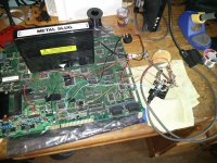
Just wanted to update everyone that I've now got video output! I'm quite pleased because now I know that my PSU is providing ample power, that my MV2F wasn't damaged during shipping, and that my video setup is logical. The CMVS isn't very presentable yet, but I will definitely post pictures once it's complete. I've got my barrel connector and DIN connector each clamped in "helping hands" for testing before I mount the components into the metal housing, so it still looks like quite a mess.

pbOcktC.jpg

Next I need to wire up the audio connections from the board, as I only wired them up in my RGB cable and figured I would do them last once I got video output. I'll also need to improve the grounding setup for my video cable, as I believe there is an issue somewhere.
 

Redguard

New Challenger
Joined
Jul 7, 2013
Posts
67
I look forward to your progress. I have a 2 slot as well that I'm in the process of consolizing.
 

kuze

Sultan of Slugs
10 Year Member
Joined
Apr 20, 2013
Posts
2,557
I look forward to your progress. I have a 2 slot as well that I'm in the process of consolizing.

Very cool -- how's your consolization coming along? Wouldn't mind seeing some pictures of your progress :)

Here's a status update on my end. I fixed my grounding issue and got video working flawlessly. At first I didn't use any resistors on the RGB lines, because I wanted to see what the baseline strength of the raw video would look like through the Framemeister. It actually looked pretty good, definitely not as strong as the SNES mini RGB output, but still a bit too bright. I threw some 100 ohm resistors on the video lines next and am very pleased with the results; they are perfect for my setup, which is awesome since I already had them on hand. Next I got audio wired up and finally got to hear that sweet Neo intro sound with the MVS logo on startup.

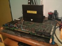
Finally some pictures of my board; the first one is of the mess I referenced above:
183448.jpg

I took some time to clean everything up a bit so I could flip the board over and wire up the audio:
204821.jpg

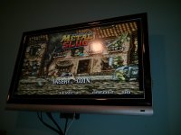
Also, a shot of Metal Slug (actually before the resistors were added):
175201.jpg

I plan to drill the holes necessary for my switch, power barrel and video output onto the back of the metal housing this weekend. After that, I'm looking to get a local company to powder coat the housing before I mount the components in place and finish it off! (Xian Xi's powder coated boards were an inspiration)

Down the road I plan on getting a nice piece of plexiglass cut to mount underneath the board, but I feel that can wait for now.
 

goombakid

Fu'un-Ken Master
10 Year Member
Joined
Oct 11, 2011
Posts
1,537
Looks good. I would've dusted/washed the board prior to finalizing it.

Also, if you want to protect the JAMMA edge, there's those plastic report covers that have that plastic slide to keep the papers together that you could use (that's how I protect mine).

429617924_048.jpg
 
Top