Neo Geo not enough voltage/current?

radiokid

n00b
Joined
Jul 30, 2016
Posts
25
In my quest to fix my other Neo Geo (which is now fixed) I bought second faulty system.

Turns out I've bagged an original 5v model, low serial number 19k or there about.

The system powers on fine, just needed a 5v PSU. I was worried he might have fried it with a higher voltage PSU. But I am wondering if my third party PSU isn't good enough, it's rated at 5V 3A but I can't confirm the current. I only get between 4.65 - 4.75v on the cartridge VCC pins and various other VCC points on system chips (B0, BIOS, LSPC0). I also spotted what I think is a 3 pin voltage regulator, not sure which pins should get what voltage but I measured two of them at 4.65 - 4.75v and the other one nearer to 4v.

I am wondering if that low voltage could be the cause of the below issue related to the power switch/reset switch.

When I press reset (and very very occasionally on switch on) I get a scrambled Neo Geo logo, either slightly thinner text, vertical lines, mirrored parts of the logo. If I let the game boot most of these issues persist in game as well. If I hit reset a few more times I can get it working perfectly, and it will stay working perfectly until I press reset again (I confirmed this by leaving games running for a hour).
 

Xian Xi

JammaNationX,
15 Year Member
Joined
Dec 1, 2005
Posts
27,750
If you are only getting 4.75v then the PSU is crap. A lot of times PSUs will say 3A but it's actually 2A and so when the device pulls more than 2A, the voltage starts dropping. Most unregulated PSUs that can push 3A will usually have a non-loaded voltage of around 5.30-5.45v, once you load it with at least 2A it usually drops to 5.0-5.1v. Of course, regulated would be best but expensive.
 

radiokid

n00b
Joined
Jul 30, 2016
Posts
25
Bit of an update. Although not really anything positive.

Given the amount of repairs I am now doing I bought a regulated bench power supply; this one https://www.amazon.co.uk/Lavolta-Variable-Linear-Bench-Supply/dp/B019KL4G6I, so I can adjust the voltage in small increments and it will maintain that voltage no matter the load. So, I know the power supply is good now.

So this is now powering the Neo Geo, I've pushed it up to 5.2v but I don't really want to go any higher. And still the Neo Geo voltage internally drops to between 4.65-4.75v regardless, and the PSU shows that it is pulling around 1.5amps. So I am still trying to find out what is causing this voltage drop inside the Neo Geo.

I'm almost certain that the seller used a 10v mega drive power supply, and although this didn't kill the system I think it must have caused some kind of damage somewhere. Now, there is nothing obvious that I can see inside; all the caps look good, no burnt chips, no signs of damage anywhere.

In my quest to find something faulty I've tested a few components starting with the B1135 transistor; which I originally thought this was a voltage regulator (because it looks like one) but it is actually a PNP transistor. There are also a couple of NPN transistors nearby. I have desoldered all of these and tested the Base, Collector and Emitters, everything checks out so these are not the cause of the voltage drop.

So, anyone got an idea of where I should be looking next?
 
Last edited:

radiokid

n00b
Joined
Jul 30, 2016
Posts
25
Power issue somewhat sorted by removing the DC jack and wiring into the solder pads underneath. New DC jack ordered, the old one did look a bit corroded so possibly it was causing some resistance.

The problem remains though, so on to more diagnostics.

Here's a video of the issue

 
Last edited:

Xian Xi

JammaNationX,
15 Year Member
Joined
Dec 1, 2005
Posts
27,750
Change the power jack and sometimes the switch is faulty.
 

GadgetUK

Ace Ghost Pilot
Joined
Sep 27, 2013
Posts
1,323
I would test the electrolytics on there! I know in my 1st gen AES nearly all the electrolytics were shot. The look OK physically but measured 40 to 50% of their uF rating and had high ESR.
 

radiokid

n00b
Joined
Jul 30, 2016
Posts
25
Given that I've already got the caps I'm gonna replace them all just in case. Fingers crossed it makes a difference. Should I also replace the big 1000uf cap on the left of the board? What does this one do; it's so much bigger than all the others!

It's a head scratcher, especially since when I get a good reset or power on everything works 100% no problems, so I am almost thinking that I should just live with it.... but then the perfectionist in me just wants to fix it!
 

GadgetUK

Ace Ghost Pilot
Joined
Sep 27, 2013
Posts
1,323
Beyond that, it must be reset timing related - maybe a chip somewhere not resetting due to bad trace or something.
 

radiokid

n00b
Joined
Jul 30, 2016
Posts
25
Beyond that, it must be reset timing related - maybe a chip somewhere not resetting due to bad trace or something.

Ok cheers for that, something else to look at. With this being an early serial model I have the B0, C0 and LSPC-A0 chips; pin outs for these being slightly harder to come by. I guess I should also look at the CPU as well... fun times ahead :)
 

Xian Xi

JammaNationX,
15 Year Member
Joined
Dec 1, 2005
Posts
27,750
Ok cheers for that, something else to look at. With this being an early serial model I have the B0, C0 and LSPC-A0 chips; pin outs for these being slightly harder to come by. I guess I should also look at the CPU as well... fun times ahead :)

Check out the Neo Geo Dev wiki, there's schematics for the AES.
 

radiokid

n00b
Joined
Jul 30, 2016
Posts
25
Check out the Neo Geo Dev wiki, there's schematics for the AES.

Yeah I've been using that site extensively. The only issue is that for the early model Neo Geo's like mine, the diagrams and pin outs are not as extensive as they are for later revisions. Specifically I'm having issues identifying Reset lines on the A0, B0 and C0 chips, I could also do with knowing if the 68000 CPU has a reset line too. The A0 is more detailed than any of the others, and I think i have identified pin 76 labeled FV/RW but I'm not really sure.

I may just have to live with the problem, this is harder to diagnose than my other system...
 
Last edited:

radiokid

n00b
Joined
Jul 30, 2016
Posts
25
Last edited:

radiokid

n00b
Joined
Jul 30, 2016
Posts
25
Replacing all the caps didn't help :(

Lets see if the above component fixes it, whenever it arrives...
 

GadgetUK

Ace Ghost Pilot
Joined
Sep 27, 2013
Posts
1,323
Replacing all the caps didn't help :(

Lets see if the above component fixes it, whenever it arrives...

It might do, but I think all it does really is invoke the reset line (or not) - I wonder if that reset line is not connecting to all the places its supposed to. Maybe one IC is lacking the reset capability, perhaps a bad trace or something.
 

radiokid

n00b
Joined
Jul 30, 2016
Posts
25
It might do, but I think all it does really is invoke the reset line (or not) - I wonder if that reset line is not connecting to all the places its supposed to. Maybe one IC is lacking the reset capability, perhaps a bad trace or something.

From the behavior I've been experiencing I would concur with that assumption Gadget. From the various schematics/pinouts I have found on the NeoGeo development wiki, it is not clear which pins are these reset ones as not all of them are labelled as such, so it's probably going to be difficult to find the traces etc.

I will keep going though...
 

radiokid

n00b
Joined
Jul 30, 2016
Posts
25
Righto.

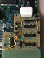
First, can someone tell me what the daughterboard on the bottom right of the Neo Geo does. My one looks different to others I have seen on the internet.

File_000 (3) (Medium).jpeg

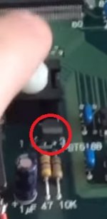
I have replaced the electrolytic and ceramic caps on this board. I noticed that before I replaced the cap circled in red, when I touched either leg with a metal object the image on screen would go crazy; a cross between loosing sync and graphics all over the place. The graphical issues looked very much like the issues I occasionally got on reset/power on; with the new cap it no longer does this.

However the components circled blue do this instead, so if I touch the cap or the pot the screen goes crazy, sometimes even reseting the console. To be fair I probably shouldn't be touching them really :) but it's my way of diagnosing things.

But, and this is the real fingers crossed moment, I think replacing the caps on this daughterboard has solved the power/reset issue I was having. I tested it by reseting about 20 times in a row, and I didn't have a single failure, so lets hope this has fixed it.

I would like to know why though, so that's why I'm asking what this daughterboard does.

Also, I still have a power issue, and I don't know why. If I connect leads straight to 2 of the 3 solder pads where the DC input jack goes then the system receives all 5v from my 5v 3a PSU, but as soon as I use the DC jack (a new one I might add) the system struggles to receive anything above 4.6v. The only difference between using the DC jack and soldering directly to the pads underneath is that the DC jack has 3 solder points (two for the barrel and one for the tip), where as when I solder directly I just solder to the one barrel and one tip pads. Since the Neo Geo is negative tip PSU then the barrel/ground pads are the ones actually getting the voltage and the tip/pin is getting ground (giving -5v into the system). I'm probably not explaining myself very well there.
 
Last edited:

Xian Xi

JammaNationX,
15 Year Member
Joined
Dec 1, 2005
Posts
27,750
It adjusts the sync rate to something a TV would like better than the original one.
 

radiokid

n00b
Joined
Jul 30, 2016
Posts
25
It adjusts the sync rate to something a TV would like better than the original one.

Isn't that the pot near the AV port? In these early generation models I thought it was something to do with the CPU. Thanks for the answer though. Wonder why changing the caps on this has solved my reset/power-on issues...
 
Top