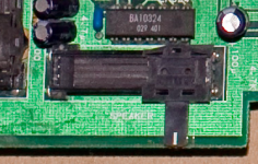
Anyone added external volume control to their mvs cab?

tenfresh

Mega Shock!!,
Joined
Jul 30, 2003
Posts
113
I'm chewing on how to best accomplish this and would love to hear how others approached it.

One idea was to extend all the connections from the slider on the board and remount in a new slot I cut in the front of the cabinet for the slider. But that seems excessive...
 

Apocalypse

Edo Express Delivery Guy
Joined
Sep 16, 2015
Posts
331
You could put an ON-ON switch on your board and add a 2 pin connector to connect an external knob.
On position of the switch connects the pot on the board to the audio IC (you need to lift a leg on the pot).
Other position connects the external pot (via the 2 pin connector you installed) to the audio IC.
 

tenfresh

Mega Shock!!,
Joined
Jul 30, 2003
Posts
113
Awesome, thanks so much for the approach — wasn't quite sure what was going on with that on-board pot. I *think* I follow – planning to take the board out in a few weeks for a bunch of project and definitely going to give this a shot. Let you know how it goes!

Hey man, do you know off hand which leg of the on-board slider-pot is the one to insert the switch between?

I confess haven't gotten around to popping the board out yet to take a close look at what goes to the audio IC — was oping to be sure I have all the proper parts on hand first!

Screen Shot 2016-02-10 at 4.03.33 PM.png
 

Xian Xi

JammaNationX,
15 Year Member
Joined
Dec 1, 2005
Posts
27,750
Why do you need to adjust the volume? It should be set at 75%.
 

tenfresh

Mega Shock!!,
Joined
Jul 30, 2003
Posts
113
Why do you need to adjust the volume? It should be set at 75%.

The cab sits in the middle of the house, so I'm constantly having to reach into coin door to tweak the volume as it gets late, or when I fire up a particularly loud game.

Ha, I also find that the volume I start playing a metal slug game on is often giving me a headache by the last level.

And an external volume dial is just a fun customization project that seemed within reach! :)
 

egg_sanwich

Windjammers Wonder
10 Year Member
Joined
Oct 9, 2012
Posts
1,379
The cab sits in the middle of the house, so I'm constantly having to reach into coin door to tweak the volume as it gets late, or when I fire up a particularly loud game.

Everyone seems to forget about the headphone jack... single best feature on a Big Red, I tells ya!
 

Apocalypse

Edo Express Delivery Guy
Joined
Sep 16, 2015
Posts
331
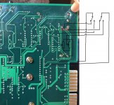
Here's a diagram I've made quickly. Check pinout of the OG pot first.
You must use a double ON-ON switch and a pot with 2 tracks (left and right):

unspecified.jpg

Also you'll have to lift the 2 upper pins of the OG pot.
 

tenfresh

Mega Shock!!,
Joined
Jul 30, 2003
Posts
113
Here's a diagram I've made quickly. Check pinout of the OG pot first.
You must use a double ON-ON switch and a pot with 2 tracks (left and right):

Also you'll have to lift the 2 upper pins of the OG pot.

Ah! I see! This is fantastically helpful. I'll definitely send picks of the final product when it's finished. This'll be such a fantastic crowning touch to a great wave up upgrades and mods the cab has seen in the last few months!
 

tenfresh

Mega Shock!!,
Joined
Jul 30, 2003
Posts
113
Just wanted to let everyone know that I finally got that volume dial installed! I was about to created the circuit you outlined by Apocalypse when I came across another less invasive option.

Which was to use this specialty item called and L-Pad Attenuator, intended for us in auto audio: http://www.parts-express.com/speaker-l-pad-attenuator-50w-stereo-1-shaft-8-ohm--260-260

This thing is simply wired in-line with the speaker wires & ground and while it doesn't cover the full range of volume, you can definitely get a range of adjustment that goes from objectively 'quiet' to 'pretty loud'.

The wiring is simple but diagrams included with the products are a little confusing.

Ignoring the numbers on the actual pins, I'll label the the pins here with letters, arranged like this when looking down at the part with the rotary shaft pointing towards you:

A B C
D E F

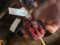
C and F both get wired into the ground (solid black wire in my cab). Individually, not passing through. In my case I wired them together, then sent one wire back into the black speaker ground wire.

Then the audio wire going to one of speakers (doesn't matter which, they're black w/ red stripe and white w/ red stripe in my cab) gets connected to B, and the corresponding wire going to board gets connected to A.

Same for the other speaker wire through D and E. Where E goes to the speaker, and D goes to the board.

Sounds confusing but follow that carefully and it should work. Here's a pic from my rigging:
IMG_5702.JPG

As far as mounting the thing, I ended up drilling a hole in the control panel and placing the dial in the far upper, right corner. Mirroring the placement of the P1 Start button on the left side. Looks classy and of-a-piece. I had to chisel out about at 1/4 inch from the particle board to the part would clear without bending the shaft sideways a little.

The knob that comes with the part is hideous of course, you can go to any radio shack that has electrical parts and pick up a bunch of replacement knob options, the sizing is pretty standard.

Enjoy!
 
Last edited:
Top