CMVS video issue?

XeD

Super Sidekicks 2
Joined
Feb 18, 2015
Posts
106
I'm building my first CMVS using a MV-1F. I am using a neobitz 2.4 and getting what I thing is weird scrolling. Component and Svideo look great except for the slight pixel shift. My problem is with composite. I get scrolling from left to right as can be seen here https://www.youtube.com/watch?v=5T8l1KM0QeM it look like im getting some kind of interference. Pics of the build are here http://s1200.photobucket.com/user/Xeno_Dragon/library/CMVS

What I have done so far:
- Use a different power supply
- Use a different neobitz
- Use the edge connector on my jamma test bench
- Install the sync cleaner (I just remove the jumper trace and install the components)
- I even use a sony PVM

any ideas?
 

Xian Xi

JammaNationX,
15 Year Member
Joined
Dec 1, 2005
Posts
27,750
You can try swapping the coupling cap on the Neobitz, it's the one to the left of the AD724, it's either 15pf or 18pf. I think 18pf.
 

GohanX

Horrible Goose
20 Year Member
Joined
Sep 28, 2001
Posts
12,511
My first cmvs did that too. I just didn't use composite.

I know, that was a lot of help.
 

XeD

Super Sidekicks 2
Joined
Feb 18, 2015
Posts
106
You can try swapping the coupling cap on the Neobitz, it's the one to the left of the AD724, it's either 15pf or 18pf. I think 18pf.

The board is silk screen for 15pf and the original cap is 18pf. Should I change it back to 15pf? Or use a different value?
 

mikey

Marked Wolf
Joined
Jun 19, 2012
Posts
215
I had the exact same issue when building encoders around any AD chips and using composite. Never found a real solution, but sometimes the issue went away randomly, and seemed to be affected if I physically picked up and rotated the CMVS or rotated the DC jack inside the barrel connector. This all caused me to think it was power related, a ground issue, or a noise/interference issue.
 

Xian Xi

JammaNationX,
15 Year Member
Joined
Dec 1, 2005
Posts
27,750
The board is silk screen for 15pf and the original cap is 18pf. Should I change it back to 15pf? Or use a different value?

18pf, you might have to get at least 3 of them as you are basically trying to match the load capacitance on the crystal which is 18pf but it depends on the actual rating since there is a slight tolerance range which is why I recommend getting 3 of them.

Edit, you can also add a trimpot to adjust it if need be.
 

XeD

Super Sidekicks 2
Joined
Feb 18, 2015
Posts
106
18pf, you might have to get at least 3 of them as you are basically trying to match the load capacitance on the crystal which is 18pf but it depends on the actual rating since there is a slight tolerance range which is why I recommend getting 3 of them.

Edit, you can also add a trimpot to adjust it if need be.

Xian Xi, your the man. I install a trimcap and I got it dial in. Anyone doing this should install the cap on the encoder itself. I original extended the wire to adjust it but that cause to much interference
 

Xian Xi

JammaNationX,
15 Year Member
Joined
Dec 1, 2005
Posts
27,750
If you can, post a photo of how you installed the trimpot as others might need help with the same issue and a pic would probably answer a lot of questions about doing it.
 

XeD

Super Sidekicks 2
Joined
Feb 18, 2015
Posts
106
View attachment 31773 I had to bend both leg flat. Solder one leg to pin 3. Wrap the other leg around the pcb to lock it in place and ran a small jumper to ground. I use one of my tv alignment tool to adjust to pot. This is the result. https://www.youtube.com/watch?v=Wi1hJMGwcYc
99% of the time I will use component or svideo, you never know when you need that 1%
 
Last edited:

Abelardo

n00b
Joined
Oct 11, 2015
Posts
30
Hello everyone, sorry for the necro bump but I'm having this exact issue with my first attempt at building a CMVS, I cannot see the attachment so I cannot figure out what XeD did, any pointers on how to tackle this?

My setup is a bit different, the system I'm consolizing is an MV1FT, RGB to composite converter is a generic one and requires +12v so I'm using a hdd power supply as it has both +12v and +5v, I can see in the hardware test screen that all red, green and blue signals are wavy but not white, any ideas? Thanks a lot!!
 

Xian Xi

JammaNationX,
15 Year Member
Joined
Dec 1, 2005
Posts
27,750
Hello everyone, sorry for the necro bump but I'm having this exact issue with my first attempt at building a CMVS, I cannot see the attachment so I cannot figure out what XeD did, any pointers on how to tackle this?

My setup is a bit different, the system I'm consolizing is an MV1FT, RGB to composite converter is a generic one and requires +12v so I'm using a hdd power supply as it has both +12v and +5v, I can see in the hardware test screen that all red, green and blue signals are wavy but not white, any ideas? Thanks a lot!!

Your encoder should have a trimpot on it.
 

Abelardo

n00b
Joined
Oct 11, 2015
Posts
30
Your encoder should have a trimpot on it.

Thanks for the reply, the encoder has 3 pots but they're for adjusting the gain on each color line, I can mess with them if needed but that is probably what you ment, right? Looks like I should add a trimpot somewhere, is a trimpot different from regular pots? A friend told me to check my grounding, maybe try another power supply? Thanks again!!
 

Abelardo

n00b
Joined
Oct 11, 2015
Posts
30
So I figured out what kind of converter I got, it's a Weiya CV-04 clone, anybody has tried those? I'll be trying S-Video tonight and see if it's any good. Wii putting a ceramic cap in the sync line help somehow? By the way Xian I followed your tutorial, thanks a lot, it was really easy to follow even though I had to improvise a bit because my model was the FT.
 

Neo Alec

Warrior of the Innanet
20 Year Member
Joined
Dec 7, 2000
Posts
12,017
Why even bother with composite and s-video anymore? I've moved on to all RGB. Use a component ybpr converter.
 

segasonicfan

Camel Slug
Joined
Feb 3, 2006
Posts
517
ah yes, this old dog! I recently found a solution to this, it was a problem that was itching me for years. First, let's understand what causes it.

This phenomenon is called Rainbow Banding or Color Artifacting or Cross Color Banding...kinda depends where you're reading. It is the result of the pixel clock of the gaming system not syncing with the 3.578Mhz color burst signal generated from your chroma encoder (or ~4Mhz if using PAL). It is also made worse by the incoming oscillator signal not matching the load capacitance of the chroma encoder circuit. The color movement you see is the final result of this color signal mixing into your Luma (Y) signal.

The only way to fix this with CMVS and Superguns is to build your own oscillator (don't use TTL can oscillators). This requires a PLL 3.58Mhz crystal, a 74HC04 and a couple other parts. The one other thing you need is an adjustable capacitor - something from 0-15pf or 0-45pf range.

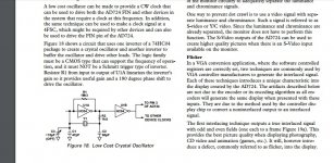
Attached is an image from the AD724 datasheet of the circuit you need. That datasheet is a great read for all this kinda stuff. Once you build that circuit and input it for SCIN (CXA1645/1145/2075 chips) or 4FSC IN (AD724/5) you can adjust that variable capacitor to solve the problem entirely- that basically makes minor tuning to the crystal to match the load capacitance at the chip.

Additionally, a luma trap helps with this issue. By making a filter around the clock burst frequency in the luma signal, rainbow artifacting is greatly reduced. There is a tradeoff of lower resolution however, because Luma uses some of that frequency to provide video information.

Hope that helps! I was stuck on this bug for a long time.

-Segasonicfan
 

Attachments

  • CNVS fix.jpg
    CNVS fix.jpg
    177.9 KB · Views: 22
Top