Village idiot needs your help: consolized MVS not working, can't figure out soldering

team_andromeda

Armored Scrum Object
Joined
Jul 26, 2015
Posts
257
First off, I apologize for stinking up the forum with the garbage I'm about to post.

I got my MV2F in the mail yesterday and I immediately set out to test out if I could consolize it with some parts I had on hand.

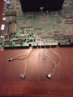
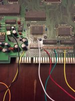
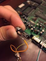
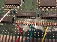
Using JNX.com's guides, I soldered a few wires and figured I was good. Turns out I can't figure out where to solder the wires on this power jack I bought and I am worried I just destroyed a perfectly good console and/or the PSU I bought. Can anybody tell me which pins are correct? Here are some pics of the jack and of my horrible soldering job elsewhere.

Spoiler:

IMG_0761.JPG
IMG_0762.JPG
IMG_0763.JPG
IMG_0764.JPG


I believe that my soldering job is terrible and also that the cables aren't going to the right place on the power jack.

I bought the following PSU and jack from DigiKey:
PSU
Power Jack

My soldering iron was set to 650 degrees and I was having trouble getting the solder to stay on the board. It was just getting "sucked up" onto the iron mostly with only a little going on the board. I'm looking elsewhere for the kindergartner's guide to soldering before I ruin my board.

Once I figure out where to solder wires on the jack, I will have to see if I soldered the correct wires to the correct spots on the 8pin DIN connector I bought.

If anyone has any recommendations besides killing myself, I'd love to hear it. I'm going to stop messing with this board until I get a better hand at soldering just in case the board is still usable.

Thanks!
 
Last edited:

team_andromeda

Armored Scrum Object
Joined
Jul 26, 2015
Posts
257
have you turned it 5V only?

Yeah, I flipped the board over and soldered a pin to a trace I scraped. I didn't think to take a pic of that to upload here. I will have to do that later when I get back home, maybe I didn't do that one right and it's requiring more power...
 

aha2940

AH, A, COLUMBIAN!,
Joined
Dec 15, 2013
Posts
2,528
Are you sure of the voltage polarity you are sending? just unsolder the jack, connect it to the power supply and test which pins are 5V and ground, then resolder properly. Also, how many amps is the power supply you are using?

Regards.
 

team_andromeda

Armored Scrum Object
Joined
Jul 26, 2015
Posts
257
Are you sure of the voltage polarity you are sending? just unsolder the jack, connect it to the power supply and test which pins are 5V and ground, then resolder properly. Also, how many amps is the power supply you are using?

Regards.

Yeah, when I get home I'm going to whip out the multimeter and check that. It's a 5V/3A power supply, which I hear is enough to do the job :o
 

aha2940

AH, A, COLUMBIAN!,
Joined
Dec 15, 2013
Posts
2,528
Yeah, when I get home I'm going to whip out the multimeter and check that. It's a 5V/3A power supply, which I hear is enough to do the job :o

Yep, 5V 3A is enough for a consolized 2-slot. Hopefully you did not fry anything when testing.

Regards.
 

Xian Xi

JammaNationX,
15 Year Member
Joined
Dec 1, 2005
Posts
27,750
For the power jack, when looking at it from the solder side, if the tabs are in a [ _ ] shape then left is not connected, bottom is ground and right is +5v.
 

team_andromeda

Armored Scrum Object
Joined
Jul 26, 2015
Posts
257
For the power jack, when looking at it from the solder side, if the tabs are in a [ _ ] shape then left is not connected, bottom is ground and right is +5v.

With this expert advice, the power LED lights up on the board! Still no video though....I have composite sync, red, green and blue going to the DIN connector, I'm looking up now if I need to connect anything else to get it to work through my Framemeister.
 

Xian Xi

JammaNationX,
15 Year Member
Joined
Dec 1, 2005
Posts
27,750
If you're using a framemeister, red, green, blue, sync, ground, audio if you want sound as well.
 

team_andromeda

Armored Scrum Object
Joined
Jul 26, 2015
Posts
257
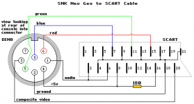
Well, still no video just the power LED turning on. I wired up RGB, sync and ground according to this diagram.

neogeo.png

I have already resoldered my connections. No clue what to do now.

EDIT: I put the sync to pin 7 from the area JNX site said to :\
 

Xian Xi

JammaNationX,
15 Year Member
Joined
Dec 1, 2005
Posts
27,750
Just remember that whatever pinout you use for the socket also has to match the cable you are using. If you aren't making a custom cable yourself, most likely it's using pin 3 for sync.
 

team_andromeda

Armored Scrum Object
Joined
Jul 26, 2015
Posts
257
Just remember that whatever pinout you use for the socket also has to match the cable you are using. If you aren't making a custom cable yourself, most likely it's using pin 3 for sync.

That did it, man. Thanks a ton! Video is working now to tweak some things.....
 

Syn

There can be only one.
10 Year Member
Joined
Jan 21, 2009
Posts
9,090
Now that your problem is resolved, you need 10,000 posts to earn the title "village idiot".

Edit: Post some pics when you get a chance.
 
Last edited:

team_andromeda

Armored Scrum Object
Joined
Jul 26, 2015
Posts
257
This has been a great learning experience! My soldering has improved as well.

Now that I have two cartridges in my MVS I see that using the select button for credits no longer works, will I have to install a credit button to work around this without putting the unibios in AE mode?

I was already thinking of doing this just for my NG Dev Team games since they won't take credits from unibios.

EDIT: I read the manual, found out more than one game shuts off adding credits with select, and I had to o into soft dip settings to be able to switch games any time. Now I'm just figuring out where to solder a button to the board to add credits with each press...
 
Last edited:

team_andromeda

Armored Scrum Object
Joined
Jul 26, 2015
Posts
257
AH ! Looks like I need to solder buttons to the 26 and 'd' JAMMA pins for P1 and P2 coins. Does anybody know where else I can solder these on the board to not clog up the JAMMA connector?

EDIT: Also, does the other end of the button go to ground? Or 5v? It's a wonder I've made it this far in life.
 
Last edited:

aha2940

AH, A, COLUMBIAN!,
Joined
Dec 15, 2013
Posts
2,528
EDIT: Also, does the other end of the button go to ground? Or 5v? It's a wonder I've made it this far in life.

Hi

All buttons in the Neo are active low, which means they get activated when connected to ground. It applies to the controllers buttons, the coin buttons, test and service. Do not connect them to 5V, you'll damage the board.

Regards.
 

Xian Xi

JammaNationX,
15 Year Member
Joined
Dec 1, 2005
Posts
27,750
AH ! Looks like I need to solder buttons to the 26 and 'd' JAMMA pins for P1 and P2 coins. Does anybody know where else I can solder these on the board to not clog up the JAMMA connector?

EDIT: Also, does the other end of the button go to ground? Or 5v? It's a wonder I've made it this far in life.

Just flip hard dip 7 and put it in freeplay mode.
 

GohanX

Horrible Goose
20 Year Member
Joined
Sep 28, 2001
Posts
12,495
I didn't see any mention of resistors for the rgb lines. I used 75 ohm on mine to get a nice image but you can also lower the A/D on the mini to around 90 or 100 to compensate for now if the image looks washed out
 

kuze

Sultan of Slugs
10 Year Member
Joined
Apr 20, 2013
Posts
2,553
I didn't see any mention of resistors for the rgb lines. I used 75 ohm on mine to get a nice image but you can also lower the A/D on the mini to around 90 or 100 to compensate for now if the image looks washed out

I used 100 ohm on mine and had great success, since I already had some on hand. Thanks to James for the tip.
 

team_andromeda

Armored Scrum Object
Joined
Jul 26, 2015
Posts
257
I got the video toned down a bit with some 100ohm resistors, and I accidentally put one inline with the 5v wire to the video too....

But now I'm having video issues! It's 90% perfect, but there are three faint horizontal lines in the picture, at the very top middle and bottom of the screen. I've resoldered my connections and I can't think of what could be causing it :\

I'm stumped!! And thank you everyone so far, you've all been a HUGE help :)
 

Xian Xi

JammaNationX,
15 Year Member
Joined
Dec 1, 2005
Posts
27,750
It sounds like you are describing one of the different scanline effects.
 

team_andromeda

Armored Scrum Object
Joined
Jul 26, 2015
Posts
257
It sounds like you are describing one of the different scanline effects.

Hmm, maybe. For some reason I don't see it on my AES console when I use the same cable and Framemeister settings though! I'll have to check and see if turning off scanlines will get rid of them, but idk why they would only show on the MVS :/

EDIT: I found a few potential solutions, I'll post my results here tomorrow when I have some time to test them :)
 
Last edited:
Top