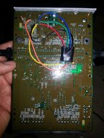
Nintendo 64 RGB mod issue (all issues resolved)

BladeDancer314

Windjammers Wonder
Joined
Dec 8, 2013
Posts
1,399
ok so I decided to RGB mod my N64 but I've ran into an issue.

after I hooked up everything (I'm using the RGB amp) I'm getting a black and white picture when I use a scart rgb to component transcoder and when I try straight RGB on my PVM I also get black and white and the PVM has trouble syncing.

also, if I try to use regular composite the picture is really, really dark.

if I cut the power to the amp the composite picture goes back to normal (brightness wise).

when I'm getting RGB out thru the amp all 3 lines are putting out around 1.8 volts at all times

the scart cable has capacitors in it (220uf) on each of the RGB lines
 
Last edited:

Skips

Belnar Institute Student
Joined
Aug 8, 2012
Posts
1,248
ok so I decided to RGB mod my N64 but I've ran into an issue.

after I hooked up everything (I'm using the RGB amp) I'm getting a black and white picture when I use a scart rgb to component transcoder and when I try straight RGB on my PVM I also get black and white and the PVM has trouble syncing.

also, if I try to use regular composite the picture is really, really dark.

if I cut the power to the amp the composite picture goes back to normal (brightness wise).

when I'm getting RGB out thru the amp all 3 lines are putting out around 1.8 volts at all times

the scart cable has capacitors in it (220uf) on each of the RGB lines

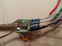
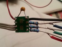
Please post some detailed pictures of everything so we can see whats going on. Also here are some pics of my mod, maybe it will help you. I also have sync ran to the composite video pin straight from the encoder, it is up top so its not in the picture.


BladeDancer314

Windjammers Wonder
Joined
Dec 8, 2013
Posts
1,399
skips I taped right onto the video chip and I took 5v and ground from the av connector

I will get pictures
 

BladeDancer314

Windjammers Wonder
Joined
Dec 8, 2013
Posts
1,399
btw thats not how I intended to leave everything, i was just hooking it up quickly to see if it worked.
 

Skips

Belnar Institute Student
Joined
Aug 8, 2012
Posts
1,248
btw thats not how I intended to leave everything, i was just hooking it up quickly to see if it worked.

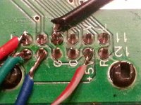
Give this a try. First see if you get unamped RGB properly. Remove the amp and go to the bottom of the PCB and tap RGB from where I did. R8 is red, R9 is green, R10 is blue. This should get you a darker RGB picture. If this works then you know your problem is with the amp. Try powering it and grounding it where I did. C109 is 5v and the wire on c74 is ground. Make sure you tap the same ends of the capacitor that I did. If you still get a messed up picture then the problem is definitely your amp. At that point you may have it backwards on the SOP PCB and are not using the correct pins (although from what I can see by following what traces that are visible it does look correct). It is also a possibility the amp itself is not working right so give all that a try.

Also some tips on soldering. Make sure that you are heating the tips of those wires then touching solder to the wire itself. You need to tin the wires correctly for them to be 100%. You want to tin both the wire and the item you will be soldering to and NEVER apply solder to the iron unless its to initially tin the iron to prevent the tip from oxidizing. You never want to use the iron itself to try and transfer solder from one item to another, this will create cold solder joints. Also trim the ends down a bit. If something jostled that system that blue line could cause a short on ground or green. I know you said this is not permanent but I figured I would be safer than sorry and say it all anyway.
 
Last edited:

Pasky

Fug:DDDDD,
Joined
May 5, 2013
Posts
2,844
You have no ceramics on the input to that amp. Put a 0.1uF or 0.01uF in series with each color line on the input to the amp.
 

BladeDancer314

Windjammers Wonder
Joined
Dec 8, 2013
Posts
1,399
Skips, I will build a second amp and mount it to the points in your pictures.

Pasky, I was under the impression that there's no need for ceramics on the input of the RGB lines
 

Pasky

Fug:DDDDD,
Joined
May 5, 2013
Posts
2,844
They're necessary to remove the DC offset on the video lines, the Amplifier is expecting that. Most people dont have them on the amp because they grab the RGB signal on the back of the board after the ceramics on the N64 PCB itself, so they're still there, just using the existing ones. Also, your composite picture is really really dark now because you wired straight to the RGB input lines on the encoder, effectively halving the R, G B levels (half going to your amp, half going to the encoder). If you plan to only use RGB for now on, this is fine, if not, rewire them to the back of the board near the multi out.
 
Last edited:

BladeDancer314

Windjammers Wonder
Joined
Dec 8, 2013
Posts
1,399
ok, I will tap RGB on the bottom of the board instead of the video chip, I'll do it when I get home tonite.

I hope that resolves this issue.
 

ApolloBoy

Edo Express Delivery Guy
Joined
Feb 15, 2012
Posts
331
I don't think I've ever done the RGB mod from the top of the board, I much prefer the other way because you can cover up the amp in heat shrink and tuck it inside the shielding. Makes it real nice and tidy that way.
 

BladeDancer314

Windjammers Wonder
Joined
Dec 8, 2013
Posts
1,399
ok quick update.

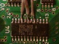
I removed the RGB wires from the feet on the video chip since everyone suggested that way.

I wired RGB from the bottom straight to the av multi out and I was able to get rgb but it was a weak signal.

I removed the old amp and soldered another one and rewired everything to match skips pictures.

I now have a strong RGB signal coming out from the av multi out, looking fantastic on my 20M2MDU and on my crt tv using a scart to component transcoder.

I still have to trim the wires and resolder them so the job is decent and I can leave the amp on the bottom, but that should not be too much of a problem.

I want to thank Skips, Pasky and ApolloBoy for taking the time to help.


tomorrow I'm doing s-video and RGB on my SNES mini.
 

kuze

Sultan of Slugs
10 Year Member
Joined
Apr 20, 2013
Posts
2,556
Please post some detailed pictures of everything so we can see whats going on. Also here are some pics of my mod, maybe it will help you. I also have sync ran to the composite video pin straight from the encoder, it is up top so its not in the picture.


Those pics are very helpful. I'd only seen the method of soldering to the video chip but this is much cleaner. Will definitely go this route when I get around to rgb modding my n64! Cheers
 

Pasky

Fug:DDDDD,
Joined
May 5, 2013
Posts
2,844
Ya, it's just a shame there isn't much improvement over S-video with the N64, everything still looks like a blurry mess in RGB.
 

BladeDancer314

Windjammers Wonder
Joined
Dec 8, 2013
Posts
1,399
I went ahead I did the RGB mod on the SNES mini and this time it went much better and it seemed just simpler, everything working good so far consoles are already put back together.

EDIT: one thing I did notice is that the N64 seems to be sending more voltage than my 20L5 and 14L5 PVM's can handle, every time there's a white screen or just a predominately white pictures it loses sync.

my 20M2MDU PVM has no such problems and neither does my Sony tv with the transcoder, I wonder if I can add another set of resistors to the scart cable to help remedy this?
 
Last edited:

Pasky

Fug:DDDDD,
Joined
May 5, 2013
Posts
2,844
IIRC, there's a 5V input near the encoder on a regulator, that takes the 5v Input and drops it 3.3V for the N64's encoder. You can grab the 5V from that instead. But...why do you even need 5V on the scart cable?
 

BladeDancer314

Windjammers Wonder
Joined
Dec 8, 2013
Posts
1,399
IIRC, there's a 5V input near the encoder on a regulator, that takes the 5v Input and drops it 3.3V for the N64's encoder. You can grab the 5V from that instead. But...why do you even need 5V on the scart cable?

I use the 5v line on the scart cable to power the transcoder lol
 

Skips

Belnar Institute Student
Joined
Aug 8, 2012
Posts
1,248
I went ahead I did the RGB mod on the SNES mini and this time it went much better and it seemed just simpler, everything working good so far consoles are already put back together.

EDIT: one thing I did notice is that the N64 seems to be sending more voltage than my 20L5 and 14L5 PVM's can handle, every time there's a white screen or just a predominately white pictures it loses sync.

my 20M2MDU PVM has no such problems and neither does my Sony tv with the transcoder, I wonder if I can add another set of resistors to the scart cable to help remedy this?

I am using a 20L5 and I use the mod I posted above on it. This sounds like a common sync issue on the 20L5, its kinda picky. Are you using Composite sync or Composite video for sync? Also is the N64 connected directly to the PVM or do you have it running through something like an LM1881n? If the scart cable is using composite video for sync try switching it to Composite Sync. Composite sync can be pulled from pin 14 on the VDC-NUS A. I unfortunately have a scart cable from that lady in Florida and she glued the SNES AV connector shut. To get composite sync I had to cut the trace on the Composite video pin on the AV socket the run Composite Sync from pin 14 on the VDC-NUS A to the composite video pin on the AV socket. You can just solder the wire to the topside of the AV socket so its clean and not wrapped around the N64 PCB.

So basically if you are not using composite sync try switching to it. You don't want to use composite video for sync anyway because doing so on the N64 causes crosshatching. You will get a better picture using composite sync. The picture gets a lot less muddy looking without the crosshatching.
 
Last edited:

BladeDancer314

Windjammers Wonder
Joined
Dec 8, 2013
Posts
1,399
I'm not using a lm1881 and it looks like it's using composite video for sync, let me try to switch it to composite sync
 

BladeDancer314

Windjammers Wonder
Joined
Dec 8, 2013
Posts
1,399
well crap, my scart cable is not pulling csync at all, its not wired for it. so i might have to get the lm1881n
 

Skips

Belnar Institute Student
Joined
Aug 8, 2012
Posts
1,248
On the scart end sync uses the same pin as composite video. On the SNES end (if you can get it open) just swap the wire on the composite video pin to the sync pin. If you cant get it open to switch it you can also do what I did and cut the composite video trace on the N64 PCB then run composite sync to the composite video pin on the AV Connector.
 

BladeDancer314

Windjammers Wonder
Joined
Dec 8, 2013
Posts
1,399
OK I cracked open the av multi out on the scart cable and rewired composite video pin 9 to pin 3 and it just made it worse.

EDIT: forgot to mention that only the N64 gives me this issue, the SNES mini with the same cable plays fine

DOUBLE EDIT: The SNES mini just made the 20L5 lose sync/picture, so it also does it, just not as much as the N64
 
Last edited:

Skips

Belnar Institute Student
Joined
Aug 8, 2012
Posts
1,248
I snapped this pic before I was finished with it today.


View attachment 13435

For the SNES mini try pulling sync right off the encoder pin to make sure you are indeed pulling Composite sync correctly. That yellow wire you have connected to the sync pin on the SNES looks like its attached to the amplifier, or maybe it is covering it up. Either way pull sync from pin 7 on the video encoder.

On the N64 you may need to run Composite sync from pin 14 on the VDC to the multiout, I cant remember if Sync actually goes through to the port.

If it still does not work after that check to make sure you have it on the correct pin in the SNES connector then check the scart end to make sure Composite Video/Sync ground is connected properly. You can check if you have it connected to the correct pin by plugging in the SNES cable then testing for continuity from the bottom of the AV port to the SCART connector.
 
Last edited:
Top