Neo Geo AES 3.3 interferences on screen

Green Beret

Fio's Quartermaster
Joined
Feb 27, 2013
Posts
498
I have changed recently caps and resistors on my console to optimise RGB contrast. I discovered I have some very light image distortion vertical-diagonal lines on RGB. I also have black and white composite.
My motherboard is 3.3.
Can anybody help?
 
Last edited:

Green Beret

Fio's Quartermaster
Joined
Feb 27, 2013
Posts
498
Update:
Put the console to my other BVM crt and the color is fine. I suppose there where some settins that wanted adjustmentn to the previous BVM crt...
Now about the diagonal lineswhich are like interferences shape.
I changed the jpn PSU, that worked with a converter 220v to 100v, with a pal SNK original PSU 5v 3A I found on ebay and the lines became less. Then put the PSU's electricity cable to an APC surge/arrest protector and lines became very hard to spot. Maybe if I didn't know I wouldn't have seen them, but still there.
If I remove the phones stereo jack that leads to a speaker system lines become very angry again. Poor image.
WTF is going on?
 

RockstarRunner

Wind Jammin' All Night",
Joined
Mar 25, 2004
Posts
645
Are you using composite video for sync? This can cause interference in your image like you describe. Use composite sync with a buffer instead, it should help. A nice shielded cable is good too.
 

Green Beret

Fio's Quartermaster
Joined
Feb 27, 2013
Posts
498
Are you using composite video for sync? This can cause interference in your image like you describe. Use composite sync with a buffer instead, it should help. A nice shielded cable is good too.
I have connected the Neo using bnc male to scart female cable that I bought from someone making them in UK. I had an RGB cable without shield but then I bought another with shield. No difference.
If I use just composite there are no interferences. In RGB there is the problem.
My jpn N64 connected with S-video has also a slight interference problem.
My pal megadrive RGB, pal Gamecube RGB, pal wii component, pal Xbox 360 component, have a clear perfect image.

What is "composite sync with a buffer". I think this might be the key for my problem. I have lots of AES games that look shitty...I can't get a 100% satisfaction from my NEO
I also aquired a super famicom with RGB cable but had no time to check it out...
 
Last edited:

Xian Xi

JammaNationX,
15 Year Member
Joined
Dec 1, 2005
Posts
27,750
For a 3-3, I recommend an RGB bypass as the RGB output is so dim on a 3-3, it should also eliminate any artifacts. On some occasions I've even added a video amp.
 

Green Beret

Fio's Quartermaster
Joined
Feb 27, 2013
Posts
498
For a 3-3, I recommend an RGB bypass as the RGB output is so dim on a 3-3, it should also eliminate any artifacts. On some occasions I've even added a video amp.
How I am going to do that. Do I have to cut some traces?
 

Xian Xi

JammaNationX,
15 Year Member
Joined
Dec 1, 2005
Posts
27,750
You don't need to cut anything. Just run the RGB signals before the 6.8k resistors to the AV socket.
 

Green Beret

Fio's Quartermaster
Joined
Feb 27, 2013
Posts
498
You don't need to cut anything. Just run the RGB signals before the 6.8k resistors to the AV socket.
Is it the same as your guide: RGB Bypass Mod for Your AES Board Revision 5 to 7 ?
Are they the same pins? If yes, the only thing I have to do is to just wire those pins togeather, like blue to blue, green to green etc? Do I need to also connect the 82ohm resistors beacause I have changed caps from 100 to 470 and resistors to what Sony recommends.
Thanks James
 
Last edited:

Xian Xi

JammaNationX,
15 Year Member
Joined
Dec 1, 2005
Posts
27,750
Is it the same as your guide: RGB Bypass Mod for Your AES Board Revision 5 to 7 ?
Are they the same pins? If yes, the only thing I have to do is to just wire those pins togeather, like blue to blue, green to green etc? Do I need to also connect the 82ohm resistors beacause I have changed caps from 100 to 470 and resistors to what Sony recommends.
Thanks James

One of the cleaner ways to do it is pull the caps up a little about 4mm off the board and stick out the leg that goes to the encoder and then solder a wire from the leg to the appropriate 6.8k resistor for that color.
 

Green Beret

Fio's Quartermaster
Joined
Feb 27, 2013
Posts
498
One of the cleaner ways to do it is pull the caps up a little about 4mm off the board and stick out the leg that goes to the encoder and then solder a wire from the leg to the appropriate 6.8k resistor for that color.
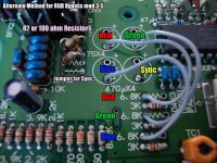
I want to understand your mod. The mod is to remove 3 caps, red, blue, green for ever and then connect the minus of where the cap was with the 6.8 resistor of each color like this picbypassrgbalt.jpg Sorry but I am a rookie at electonics.

But you suggest for a cleaner way just to put out the + positive leg of each cap and solder a wire from the leg to the 6.8 resistor.
I can leave the sync cap as it is to have composite. Is it correct?

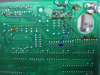
Do I need to do also wiring to the back of the board?bypassrgb57.jpg
 
Last edited:

Xian Xi

JammaNationX,
15 Year Member
Joined
Dec 1, 2005
Posts
27,750
Correct, just pull out the positive leg and solder to it. Keeping the cap in the circuit helps with the ac coupling. You do not need to remove the 6.8k resistors btw.
 
Top