Fixing a MV2F. Need help, please.

Hodor

Cheng's Errand Boy
Joined
Nov 18, 2013
Posts
112
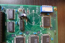
Several weeks ago, I bought a MVS MV-2F board from Ebay. The seller claimed it was fully functional and 100% working. When the board arrived, I found a minor leak in the battery so I removed it. No other damage was noticed and the components nearby were in an apparently good shape.

Well, on the first boot without the battery a Backup RAM Error 5555 5540 is shown. After a proper cleaning and the Unibios plugged in, the Backup RAM Error changes and shows 5555 5500. Today, once the battery holder and the coin cell are installed I have a new Backup RAM Error: 5555 5580.

I have taken some pictures of the errors too:

15evc06.jpg


307w6yt.jpg


2q9xxc1.jpg


2m5mrt5.jpg


9izdsk.jpg


None of the green thin lines near the battery look like damaged or cut nor the resistors or any other component. I suspect the problem comes from both Sony SRAM chips beside the BIOS but I´m not totally sure about it.

On the other hand, I have found several SRAM chips in Ebay in case I need to replace them but I do not know if they are compatibles:


http://www.ebay.es/itm/CXK58257AM-12L-Manu-SONY-Encapsulation-SOP-28-32768-WORD-X-8-BIT-HIGH-SPEED-/120932109554?pt=LH_DefaultDomain_0&hash=item1c281d8cf2

http://www.aliexpress.com/item/CXK58257AM-12L/1313750414.html

http://www.ebay.es/itm/CXK58257P-12L-Manu-SONY-Encapsulation-DIP-28-x8-SRAM-/130830364175?pt=LH_DefaultDomain_0&hash=item1e7618ee0f

If someone can help me out fixing this problem I would be most grateful.
 

Terot

Kabuki Klasher
Joined
Apr 2, 2013
Posts
129
Looks like it could be the VRAM. I had a similar situation (the Neo-Geo logo looked all screwed up) where replacing the VRAM fixed the issue.
 

skinny503

NAM-75 Vet
Joined
Sep 22, 2013
Posts
1,003
Did you clear the back up ram after replacing the battery?


Flip all dip switches to on and then power on the board. You will see "Work Ram Test" or something like that on the screen. Let this sit for a minute or so, then turn off the machine and return all dips to normal settings... all memory clear! :)

-Nick

You can also do it by going into test mode then the hardware test. Flip through the screens until you get to one says A+B+C to clear backup ram. Simply press A+B+C at that point.

Raz
 

Hodor

Cheng's Errand Boy
Joined
Nov 18, 2013
Posts
112
Looks like it could be the VRAM. I had a similar situation (the Neo-Geo logo looked all screwed up) where replacing the VRAM fixed the issue.

Can the Backup RAM error and VRAM be related in some way? I mean, a video ram error does not have its proper message?

Did you clear the back up ram after replacing the battery?

I tried but I couldn´t, the system hangs and shows Backup RAM error before doing further action.

Thanks for replying.
 
Last edited:

skinny503

NAM-75 Vet
Joined
Sep 22, 2013
Posts
1,003
Can the Backup RAM error and VRAM be related in some way? I mean, a video ram error does not have its proper message?


I tried but I couldn´t, the system hangs and shows Backup RAM error before doing further action.

Thanks for replying.

Even with the dip switches?
 

skinny503

NAM-75 Vet
Joined
Sep 22, 2013
Posts
1,003
yes, and your supposed to let it sit for a minute or two before powering off and placing all the dip switches to the off mode. Your probably correct in thinking that there is another problem, but if we dont do the diagnostic testing correct your essentially masturbating (wasting time)


If you could get pictures of around the battery area it would really help us to. I have looked at a board every day for a week and was stumped, showed it to a friend and he pointed out a trace I looked at 20+ times and never saw it!
 
Last edited:

Hodor

Cheng's Errand Boy
Joined
Nov 18, 2013
Posts
112
yes, and your supposed to let it sit for a minute or two before powering off and placing all the dip switches to the off mode. Your probably correct in thinking that there is another problem, but if we dont do the diagnostic testing correct your essentially masturbating (wasting time)

Sorry, I do not get to the point. One second after the screen "Work RAM test" the board hangs and shows an error. I mean, does the diagnostic test runs even with that error? I´m a bit confused.


If you could get pictures of around the battery area it would really help us to. I have looked at a board every day for a week and was stumped, showed it to a friend and he pointed out a trace I looked at 20+ times and never saw it!

These two pictures have been taken some days ago before soldering the battery holder. I put you the link because of the high resolution:

http://i42.tinypic.com/1zppstj.jpg

http://i42.tinypic.com/2s98thd.jpg
 

skinny503

NAM-75 Vet
Joined
Sep 22, 2013
Posts
1,003
I didnt see anything in the pics. Im hoping xian xi will chime in and put all us noobs in our place! More pics of the board would always be welcome as the problem could be else where!

EDIT: Could you please post of pics of the battery install? I'm wondering if the battery could be a/the issue?
 
Last edited:

skinny503

NAM-75 Vet
Joined
Sep 22, 2013
Posts
1,003
I actually found something interesting! Looks even worse in the other view. Hard to tell, but I will gamble $3.50 and say that trace is damaged!
2s98thd (1).jpg
 
Last edited:

shadowkn55

Genbu's Turtle Keeper
15 Year Member
Joined
Dec 9, 2006
Posts
2,386
The ZMC2 is a graphics serializer so it'll help with picture issues but not with the backup ram problem.
 

Hodor

Cheng's Errand Boy
Joined
Nov 18, 2013
Posts
112
I didnt see anything in the pics. Im hoping xian xi will chime in and put all us noobs in our place! More pics of the board would always be welcome as the problem could be else where!

EDIT: Could you please post of pics of the battery install? I'm wondering if the battery could be a/the issue?

I´m afraid the battery is not the issue because the board has the same behaviour with and without it. In fact, the Backup RAM Error 5555 5540 and 5555 5500 have happened without the battery holder and the coin cell installed.

I actually found something interesting! Looks even worse in the other view. Hard to tell, but I will gamble $3.50 and say that trace is damaged!

Good point, but it is only dust. I´ve just checked it now.
 

Xian Xi

JammaNationX,
15 Year Member
Joined
Dec 1, 2005
Posts
27,750
Since the error keeps changing I would think the LS32/HC32 is going bad.
 

GadgetUK

Ace Ghost Pilot
Joined
Sep 27, 2013
Posts
1,323
I would check / swap the 74HC32 and the SRAM, after you've checked traces on SRAM. It's time consuming but it's worth checking the traces.
 

Hodor

Cheng's Errand Boy
Joined
Nov 18, 2013
Posts
112
Since the error keeps changing I would think the LS32/HC32 is going bad.

Thanks for giving your opinion, Xian Xi. Are these chips hard to find for replacing them? I will check the traces nearby as soon as I can.

I would check / swap the 74HC32 and the SRAM, after you've checked traces on SRAM. It's time consuming but it's worth checking the traces.

Indeed, I will. Thanks a lot!!
 
Last edited:

Hodor

Cheng's Errand Boy
Joined
Nov 18, 2013
Posts
112
Well, it´s been some time and I have fresh news to update the post.

After running continuity tests in almost every trace nearby the backup SRAM IC´s, all seem in perfect shape and no trace is cut. But, using a Logic Probe in the LS32 below the BIOS chip, I have no pulse in pins 2A, 2B, 3A, 3B, 4A and 4B. Pins 2Y, 3Y and 4Y shows a HI pulse. I don´t know if the lack of signal in pins 2A, 2B, 3A...etc is normal so if someone can help me out with this, it will be very much appreciated.

Moreover, one of the SRAM IC´s does not follow it´s truth table. Let me explain: following that table, if CE pin gives a Low and OE pin gives a High, WE pin should give a High. But, in one of the chip the WE pin has no signal.

Summing up, are the LS32 and one of the SRAM IC´s faulty? I think so but I need a confirmation, please.

Thanks a lot in advance.
 
Last edited:

GadgetUK

Ace Ghost Pilot
Joined
Sep 27, 2013
Posts
1,323
Check out my video here covering the HC32 (or LS32) - It's an OR gate, so you can work out easily enough if it's working by looking at the inputs and outputs.

Jump to about 27:30

http://www.youtube.com/watch?v=eKCqXE8WBFQ

If the inputs to the OR gates are pulsing between high and low then that could make it harder to check.

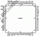
You could try forcing the RESET pin on the CPU to either a low or high (via a 4K7 or 6K8 resistor) temporarily, that might at least stop it from pulsing the inputs to your 32 chip.

You could also feed +5v through a 6k8 or 4k7 resistor into the HALT pin in order to halt the processing - that would allow (probably) to see what's going on with those OR gates. I think the HALT pin is pin 19? And I could be wrong, it might need pulling to ground rather than having 5v fed in through a resistor.

68000cqfp.gif
 
Last edited:

Hodor

Cheng's Errand Boy
Joined
Nov 18, 2013
Posts
112
Check out my video here covering the HC32 (or LS32) - It's an OR gate, so you can work out easily enough if it's working by looking at the inputs and outputs.

Jump to about 27:30

http://www.youtube.com/watch?v=eKCqXE8WBFQ

If the inputs to the OR gates are pulsing between high and low then that could make it harder to check.

You could try forcing the RESET pin on the CPU to either a low or high (via a 4K7 or 6K8 resistor) temporarily, that might at least stop it from pulsing the inputs to your 32 chip.

You could also feed +5v through a 6k8 or 4k7 resistor into the HALT pin in order to halt the processing - that would allow (probably) to see what's going on with those OR gates. I think the HALT pin is pin 19? And I could be wrong, it might need pulling to ground rather than having 5v fed in through a resistor.

View attachment 10182

Thanks a lot for replying. Before using my logic probe I had precisely watched the video you have suggested :)

However, my problem is not related with pulses that change between high and low but with the absolute lack of pulsing signal in the pins 2A, 2B, 3A, 3B, 4A and 4B. They neither show low nor high pulse, so I think the LS32 is probably faulty. In any case, I need a confirmation before removing the LS32 and put in a new one.

I have also detected a possibly wrong behavior in one of the SRAM IC´s as I have already pointed out.

Anyway, congratulations for your Youtube channel.
 
Last edited:

GadgetUK

Ace Ghost Pilot
Joined
Sep 27, 2013
Posts
1,323
My guess from looking at the picture above is the NEO-ZMC is going to have some damaged tracks. Those 3 NEO quad flat pack chips at the bottom of the photo look to have acid damage on them as well =/

Regards the LS32, I am getting confused... There's a HC32 in the BRAM part of the system, and an LS32 feeding the jumpers into the ZMC2 as far as I can see. Is that the chip you are talking about - the second one? Because I don't think it should be pulsing, unless i've missed something on the diagram. It looks like it just feeds jumper inputs into the ZMC2.

EDIT: I do see other places the LS32 is used. If in doubt just swap it out - it's a pretty cheap chip.
 
Last edited:
Top