- Joined
- Jun 9, 2004
- Posts
- 1,462
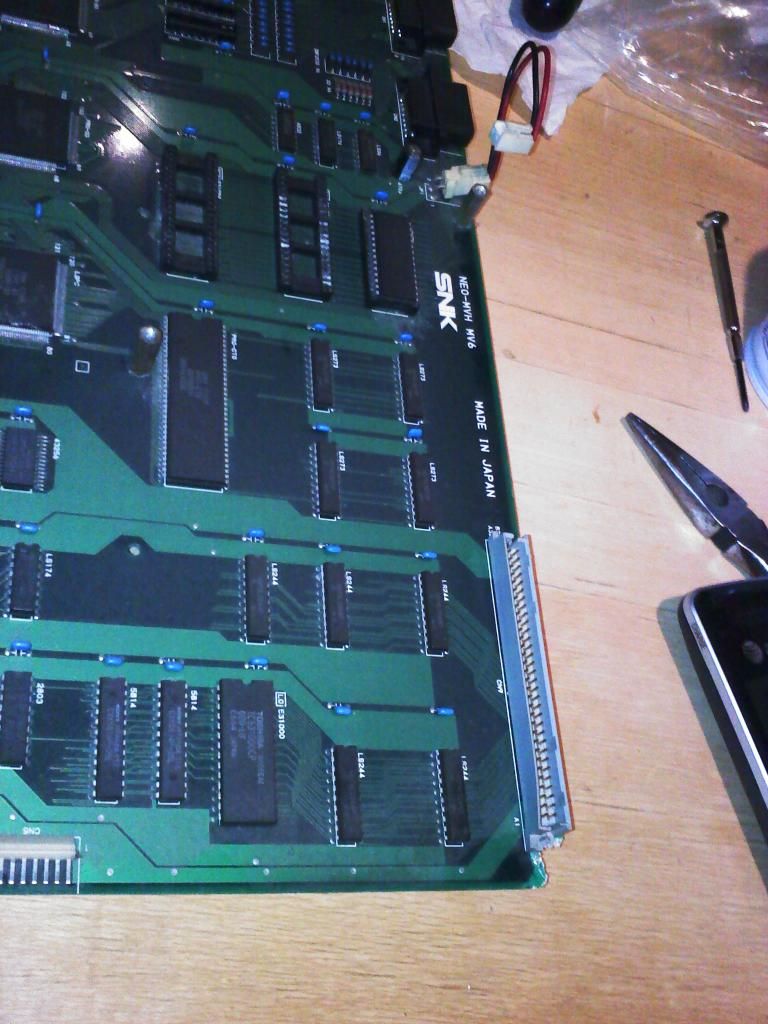
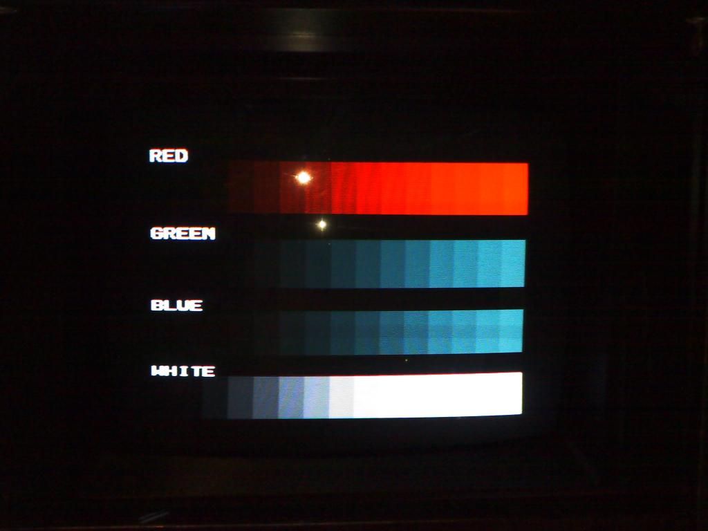
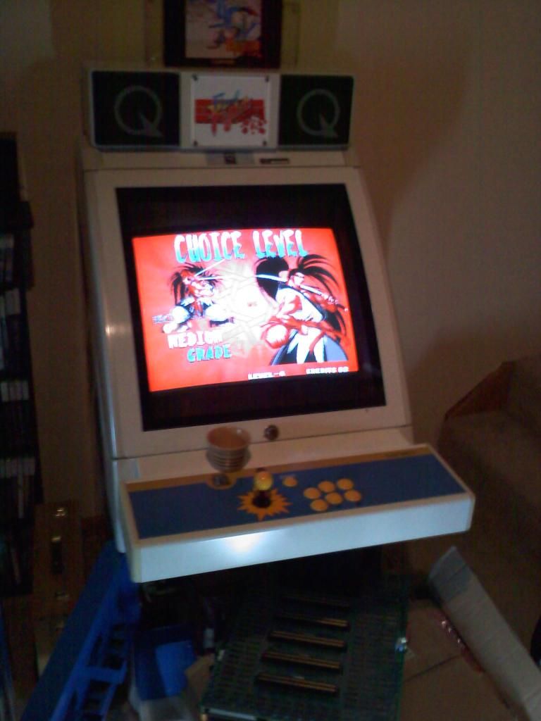
Hey I just recieved a six slot in the mail today (to replace one that I got that had some graphic glitches) and seem to have a color issue with the board.
I think its not displaying the color green. I tried out my other boards again to make sure I didn't accidentally knock something loose when removing my board and they are displaying fine.
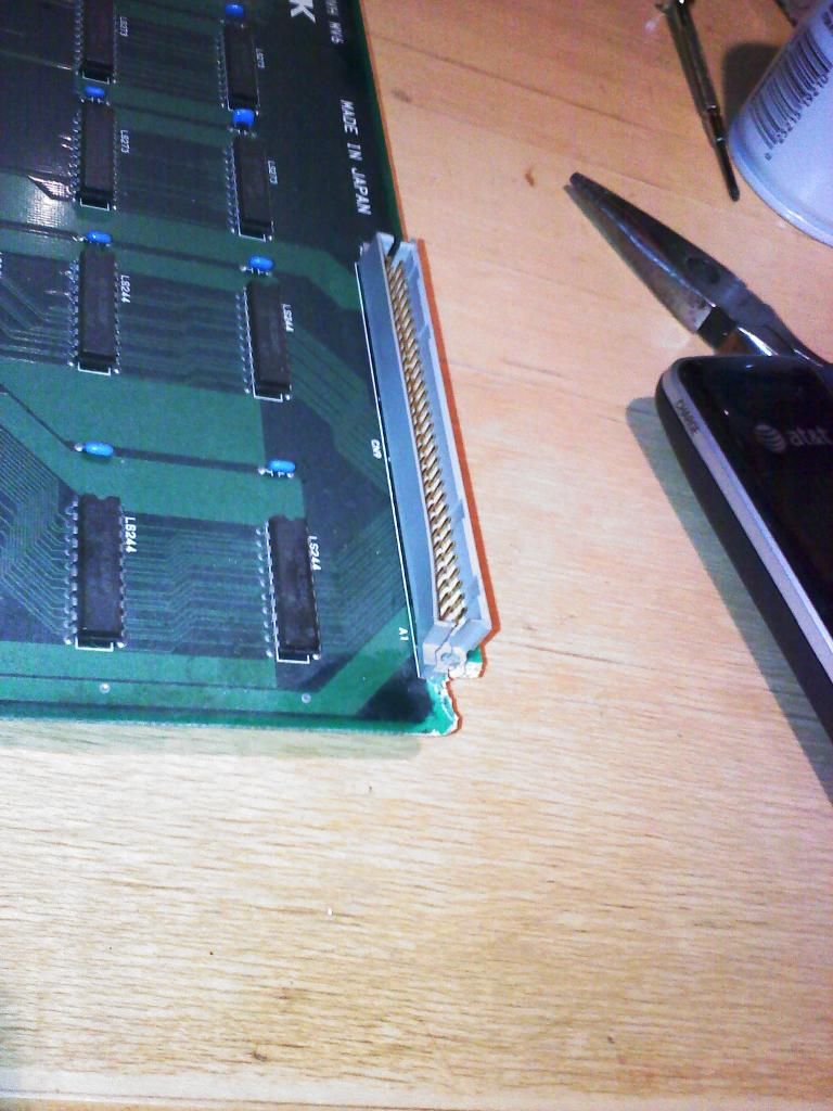
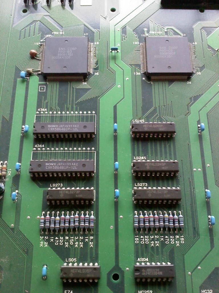
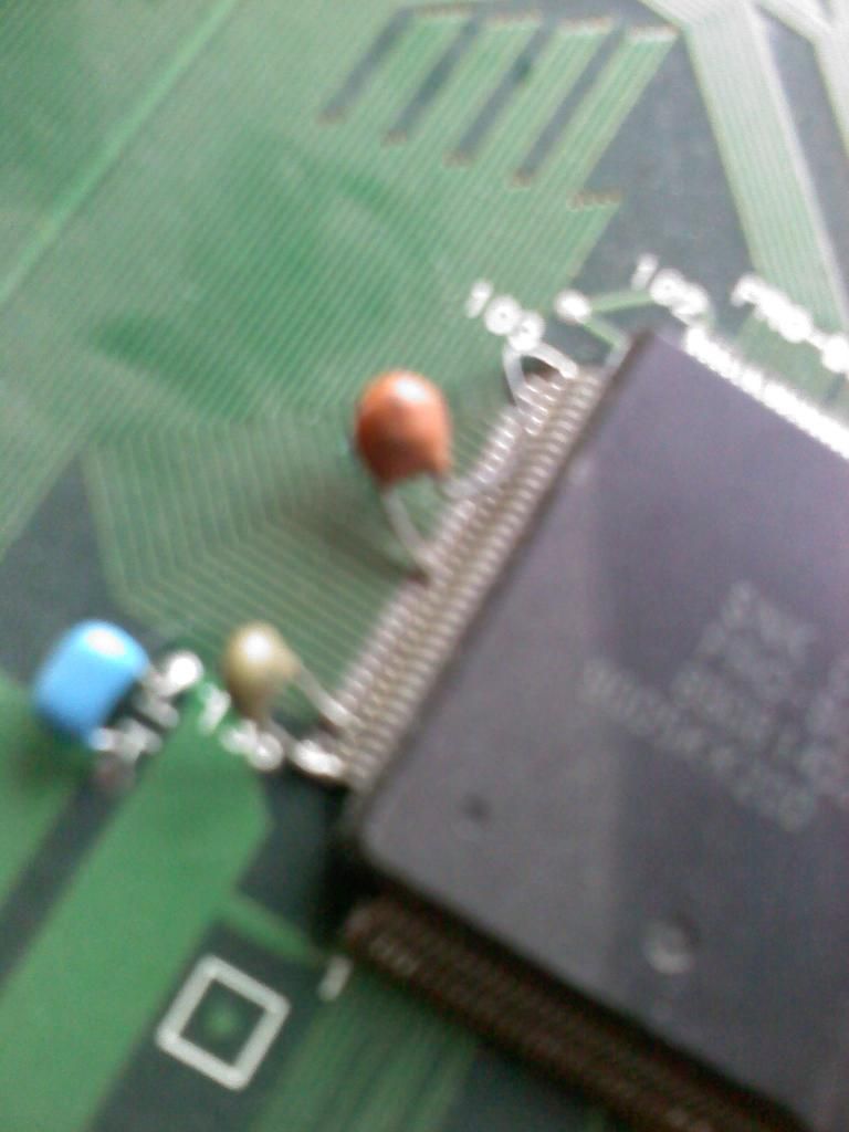
I took a closer look at the board and it seems to have a damaged corner. It had a screw that would have gone into a pcb foot but the foot was missing.
Not sure if this is the cause of the problem or not. It looks like none of the traces on the connector are near the damaged corner.
I tested out a couple of things to try and get it to display right. The first was to test the voltage. That seemed fine. I upped the voltage a little to make sure it was getting proper power. That had no effect.
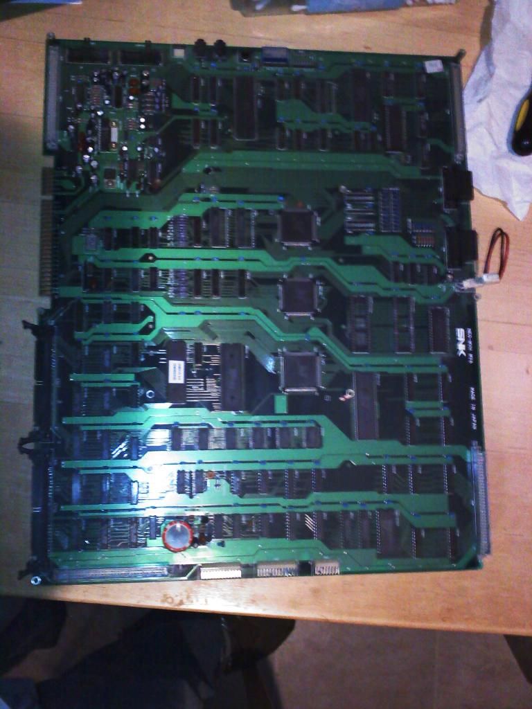
The second was to remove the top board and replace it with another six slot top board that I have to see if the trouble was with the bottom board. This had no effect as well. Which leads me to believe that the trouble is with the bottom board.
Anyone have any suggestions? Am I missing something obvious?
Any help would be greatly appreciated.
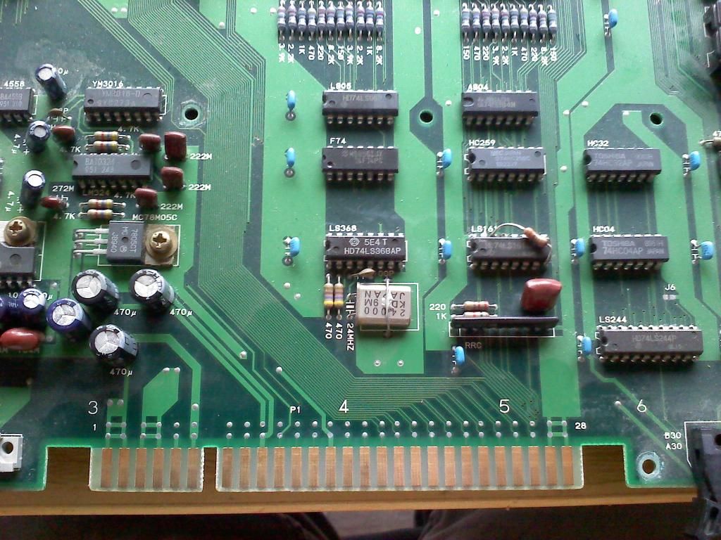
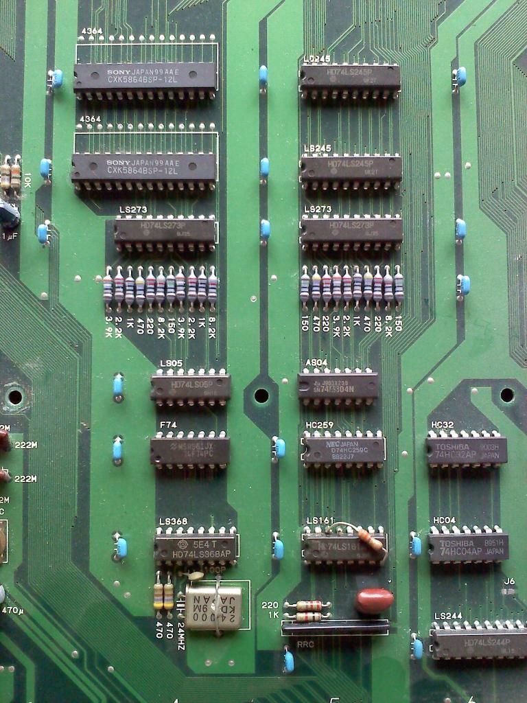
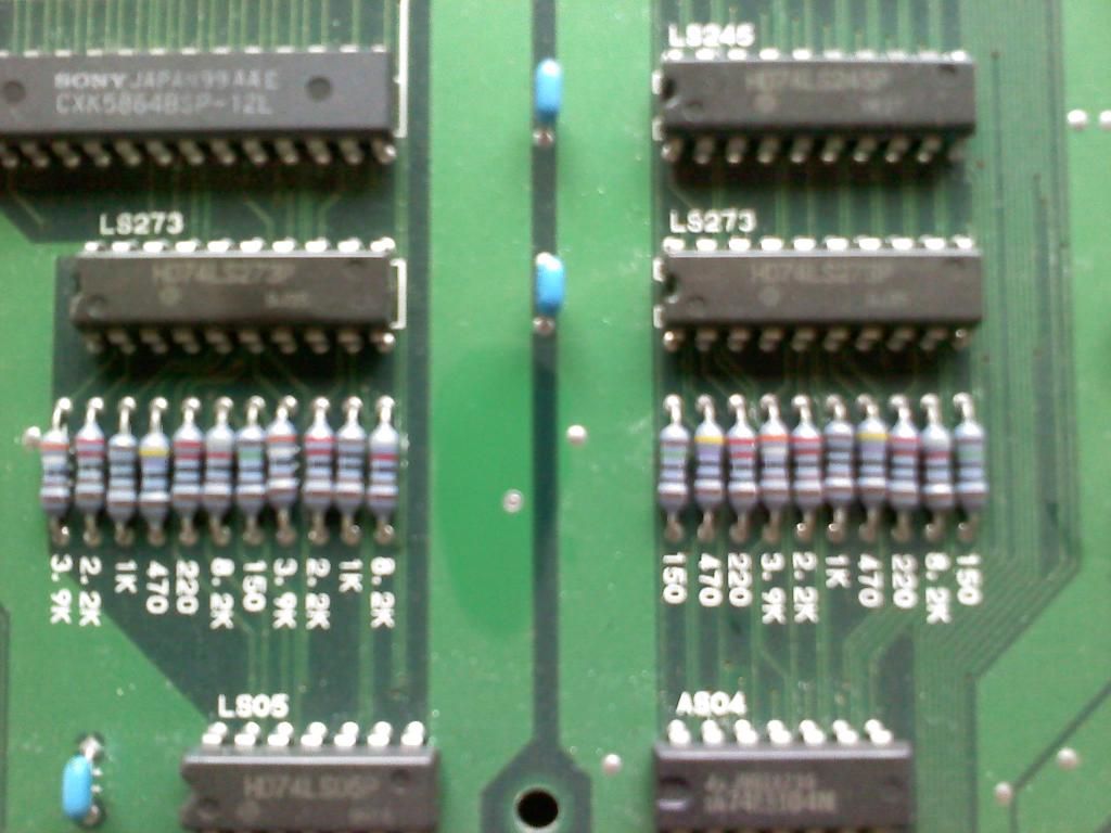
Here are some pics of the board and some comparison pics of the monitor:
Wrong color board:

Correct color board:

Wrong color board:
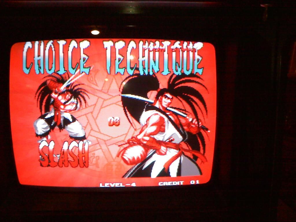
Correct color board:

I think its not displaying the color green. I tried out my other boards again to make sure I didn't accidentally knock something loose when removing my board and they are displaying fine.
I took a closer look at the board and it seems to have a damaged corner. It had a screw that would have gone into a pcb foot but the foot was missing.
Not sure if this is the cause of the problem or not. It looks like none of the traces on the connector are near the damaged corner.
I tested out a couple of things to try and get it to display right. The first was to test the voltage. That seemed fine. I upped the voltage a little to make sure it was getting proper power. That had no effect.
The second was to remove the top board and replace it with another six slot top board that I have to see if the trouble was with the bottom board. This had no effect as well. Which leads me to believe that the trouble is with the bottom board.
Anyone have any suggestions? Am I missing something obvious?
Any help would be greatly appreciated.
Here are some pics of the board and some comparison pics of the monitor:
Wrong color board:
Correct color board:
Wrong color board:
Correct color board:
Last edited:


")