MV-2F Consolizing complete! (sound issues)

Heinz

Parteizeit
15 Year Member
Joined
Feb 13, 2005
Posts
22,447
Finally completed my consolized MV-2F! after 2 years of thought, neglection, revisions and some hard work It's finally complete and ready to play!

img0047wl.jpg

Used a standard JAMMA harness and modified it so I've only got what I need, power, video and sound. Modified a Male-Male SCART cable with one side RCA, could've used a SCART breakout instead but this works just fine.

img0056ic.jpg

Good ole CD stick serves me well! Painted using an 'all surface' gloss black spray paint. Okay its not as good as a powdercoat but it does the job.

img0051g.jpg

Ohh yeah! beautiful RGB. Used 160ohm resistors on all the RGB lines as without it there was some serious colour bleeding and intensity was through the roof. I do have some 1k minipots but thought I'd try some fixed resistors first and they've worked out just fine.

img0055en.jpg

Now, this is probably not the route most people would've gone down but I decided to build a seperate arcade PSU box to power my MV-2F. Inside is a Wei-Ya switching arcade PSU, a fan and vent for cooling. 5v+, 12v+ and GND are provided by the double pin outputs. I was going to use a 5V powersupply but I didn't want to modify the board at all.

img0053hw.jpg

RCA jacks installed, R-G-B-Blanking-Sync-AudioL-AudioR. Not what you usually see on the side of a CMVS but its made only to work with my SCART-RCA cable. This design is something I'm looking to use in a future supergun project. You might notice the metal casing isn't completely flat, It is slightly damaged unfortunately but then again I'm not staring at the Neo while I'm playing.

img0054y.jpg

Back power sockets, double GND with 5v+ and 12v+.

Mounting platform is a high quality MDF which I've coated in the same paint used for the metal casing. Hexagonal mounting legs used, screws on the underside and on the top to secure them in. All connections soldered and insulated either using heatshrink and/or liquid electrical tape. Monitor used is a Loewe, model is in my sig.

Slight problem though, if my cartridges are seated a certain way I either get graphics garbage or crosshatch. I used mineral turpentine and cleaned the cartridge contacts. This made every game work without graphics problems though they still cant be seated too far in or out. Overall though I get NO SOUND from my games, test menu gives me sound in all the right speakers but games DO NOT give me any sound. I got a credit card and used mineral turpentine with fabric and then papertowel and still no sound whatsoever. Headphone jack doesnt give sound either from my games.

This MV-2F was recently recapped for audio by Channelmaniac and I have gotten audio out of it before but it's been a bit of an asshole at times.

Next thing I'm thinking of trying is a toothbrush but I don't know if it'll make a difference. Any help would be appreciated! But yeah theres my project finally finished.
 

Xian Xi

JammaNationX,
15 Year Member
Joined
Dec 1, 2005
Posts
27,750
Where are you pulling audio from? You could have ran it with just +5v and tapped it from the headphone socket.
 

Heinz

Parteizeit
15 Year Member
Joined
Feb 13, 2005
Posts
22,447
Where are you pulling audio from? You could have ran it with just +5v and tapped it from the headphone socket.

Audio is being pulled from the JAMMA, I know I could've used the headphone socket but this way works too.

I was thinking of using the +5v only mod but this project was done over such a long time I had drilled holes, stopped for 6 months, come back drilled a few more, all with different ideas of what I was going to do. Worked out I sorta butchered the back where the power sockets are so I went with the most aesthetically appealing option that wouldn't leave a gaping mangled hole in the back casing. That ended up being dual sockets which hides the horrible drill work of mine.
 

Hewitson

Metal Slug Mechanic
Joined
Mar 6, 2008
Posts
2,198
It's far more convenient to use the headphone output for consolised/superguns as it is already at approximately line level.
 

Hewitson

Metal Slug Mechanic
Joined
Mar 6, 2008
Posts
2,198
Me too. Must be very frustrating to be having problems after all that hard work.
 

Heinz

Parteizeit
15 Year Member
Joined
Feb 13, 2005
Posts
22,447
Very, it's quite annoying though I might add it keeps the girlfriend happy (she hates game sounds, even mutes her own games). At first all of my carts either didn't boot or were completely garbled without sound. After thoroughly cleaning the contacts they all worked perfectly but still no sound. My last resort is seriously cleaning the cartridge slots or (hopefully not) checking for bad traces.

Had sound from the board before and the cart slots haven't been cleaned ever, I've had this board for a number of years with it being completely unused for at least 1-2 years. I was just happy that the battery hadn't leaked. (which has been removed since)

The only thing I've got to clean the slots with at the moment is mineral turpentine which seems to be fine on my cartridges though it doesn't evaporate every quickly. I'd much rather isoproyl alcohol or something more friendly to electronics but I suppose this is fine, it isn't corroding anything.
 

rcantor77

Baseball Star Hitter
Joined
Oct 23, 2010
Posts
1,267
Nice work. I do prefer consolization done directly from the edge connector. It may not be the nicest looking but it leaves the board completely intact.

Instead of using Phonos for each line of video, for future projects why don't you look at using a 9-pin D-Sub. You then will only need to have one socket and more than enough pins for everything.

Shame about the sound though, hopefully you will get that fixed soon. Do you get anything out of the headphone socket or is it the same as the edge connector...?
 

Heinz

Parteizeit
15 Year Member
Joined
Feb 13, 2005
Posts
22,447
Nice work. I do prefer consolization done directly from the edge connector. It may not be the nicest looking but it leaves the board completely intact.

Instead of using Phonos for each line of video, for future projects why don't you look at using a 9-pin D-Sub. You then will only need to have one socket and more than enough pins for everything.

Shame about the sound though, hopefully you will get that fixed soon. Do you get anything out of the headphone socket or is it the same as the edge connector...?
Cheers mate!

For future projects I will definitely look at more compact solutions like a 9-pin d-sub. I chose RCA's because I had already drilled holes for them a long time ago. Future projects I think will be done with more planning and less time inbetween work. :emb:

Sound from the test menu is present from both the edge and the headphone socket although games produce no sound at all through either.
 

Hewitson

Metal Slug Mechanic
Joined
Mar 6, 2008
Posts
2,198
Very, it's quite annoying though I might add it keeps the girlfriend happy (she hates game sounds, even mutes her own games).
Pffft.. Chip music is the most beautiful sound in the world.
 

MKL

Basara's Blade Keeper
20 Year Member
Joined
Mar 8, 2002
Posts
3,686
http://img16.imageshack.us/img16/8144/img0053hw.jpg
RCA jacks installed, R-G-B-Blanking-Sync-AudioL-AudioR. Not what you usually see on the side of a CMVS but its made only to work with my SCART-RCA cable. This design is something I'm looking to use in a future supergun project.

Having 5v (blanking) on an RCA jack like the other ones used for RGB, sync and audio is definitely not a good idea as it could damage something if you plug one of the other cables into it by mistake and with all those jacks it doesn't seem a remote possibility.

http://img806.imageshack.us/img806/381/img0054y.jpg
Back power sockets, double GND with 5v+ and 12v+.

Your pics are really small but if those are non-polarized IEC sockets it's a terrible idea to use them for DC power. They're used for AC for a reason. Use one 3-way polarized IEC socket like these instead:

ST03UBVAAS_pho1.jpg

image.php
 

jew90

Geese's Thug
Joined
Nov 6, 2010
Posts
273
Having 5v (blanking) on an RCA jack like the other ones used for RGB, sync and audio is definitely not a good idea as it could damage something if you plug one of the other cables into it by mistake and with all those jacks it doesn't seem a remote possibility.


Your pics are really small but if those are non-polarized IEC sockets it's a terrible idea to use them for DC power. They're used for AC for a reason. Use one 3-way polarized IEC socket like these instead:

ST03UBVAAS_pho1.jpg

image.php


Damn you beat me too it!

Pretty cool! However, I would advocate NOT using identical fitting sockets for 5v and 12v supply.

Simple rule.

If it can be connected together assume at some point it will. Either by you or someone else.

Putting 12v down 5v isn:t going to be very good for the board. Or if you connect it backwards, or both!

455px-DIN-3_Diagram.svg.png


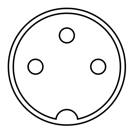
Something like this wont get mixed up and can carry both voltages.
 

SignOfGoob

Butthurt Enthusiast
20 Year Member
Joined
Sep 18, 2003
Posts
2,857
Regarding the cart slots.

When I bought my two slot I had trouble with every new game I bought for it. Even if I took the carts and apart and mercilessly cleaned them. Once they were set right they would play perfectly as long as I never touched then, but every time I changed games I would have sound or video issues, usually sound.

Eventually what I did was take a piece of sheet styrene (already had it laying around for scratch building robot models) that was the same basic thickness as an MVS PCB. I wrapped it in 2000 grit sanding film (not paper, since the grit falls off sandpaper easy). I sprayed tons of Ideal Electrical Contact Cleaner and carefully massaged the styrene/sanding film sandwich in and along the slots for a while making sure they stayed wet all the time. When I was done grinding I flushed it all out with more contact cleaner.

This has worked wonderfully. This also works somewhat well with the Saturn cart slot, although in all honestly that thing is just a pure piece of shit so you'll always have some problems.

Now I can swap carts with no problem with the exception of Pulstar. Usually its OK, but that fucker gives me shit sometimes even after its been working perfectly for hours. The sound sometimes gets quiet, and then sometimes spazzes out sounding overdriven and extremely distorted. Certain types of sounds are unaffected, some are fuct.

BTW I would avoid turpentine as its going to leave some serious residue in there after a while. Also, I have no idea what it would do to the PCB, the lacquer coating, the semiconductors, etc. In the end its going to cause far more problems than it will fix.
 

Heinz

Parteizeit
15 Year Member
Joined
Feb 13, 2005
Posts
22,447
MKL, in relation to the sockets, what is it exactly that makes these not so good for DC power?

I'll have to label the power sockets as well as the RCA's before I give it too much use, it certainly will not be used by anyone else. Seems power is probably the only thing I need to work on a solution for. Maybe the +5v mod is the way to go.

SignofZeta,

I'll definitely try this method, hopefully I can get sound working again.
 

rcantor77

Baseball Star Hitter
Joined
Oct 23, 2010
Posts
1,267
Once you get the sound working, I was thinking of ways you could sort out the sockets if you wanted to. Not criticisng your work at all, just suggesting ways to re configure it.:)

For the power you could easily change it to one socket with both inputs and then the other hole you could install an on/off switch as I assume it is on the power unit that you have built.

With the A/V on the side, you could create a new hole for din/dsub and then use the existing holes to install some pots for the RGB lines and perhaps for a test/service switch or something I need to put on mine... select up/down buttons so you can use both slots. Could even install a NeoBitz and then us the holes as Component/S-Video outputs.

Lots of options if you wanted to work on it some more.:D
 

Hewitson

Metal Slug Mechanic
Joined
Mar 6, 2008
Posts
2,198
They are no good for DC because they can be plugged in upside down!!

I would however use more than 3 way plug, you want at least 3 nice thick 5v wires. I'd suggest using connectors that are actually designed for DC power, using AC ones just looks strange and could possibly lead to someone plugging 240V into the unit!
 
Last edited:

Heinz

Parteizeit
15 Year Member
Joined
Feb 13, 2005
Posts
22,447
Once you get the sound working, I was thinking of ways you could sort out the sockets if you wanted to. Not criticisng your work at all, just suggesting ways to re configure it.:)

For the power you could easily change it to one socket with both inputs and then the other hole you could install an on/off switch as I assume it is on the power unit that you have built.

With the A/V on the side, you could create a new hole for din/dsub and then use the existing holes to install some pots for the RGB lines and perhaps for a test/service switch or something I need to put on mine... select up/down buttons so you can use both slots. Could even install a NeoBitz and then us the holes as Component/S-Video outputs.

Lots of options if you wanted to work on it some more.:D

Hey by all means I'm open to re configuring the design, over the last day I've been thinking about everything people have said. I was thinking of keeping this as a temporary solution as I really want a supergun for standard jamma and mvs. Just financially I can't fund such a project at the moment. For a supergun I definitely will not use RCA's and instead a DIN socket.

As for changing what I've already done, I wouldn't mind changing it so I only need +5v. This would simplify the power situation. Many possibilities though, I usually change things as I go along. Pretty much a WIP at all times with me.

They are no good for DC because they can be plugged in upside down!!

I would however use more than 3 way plug, you want at least 3 nice thick 5v wires. I'd suggest using connectors that are actually designed for DC power, using AC ones just looks strange and could possibly lead to someone plugging 240V into the unit!

Ahh see I already knew that, easy to fix really, I've used a permanent marker to mark off the voltage and GND lines. That and I follow the lead to make sure it is lined up correctly every time. Call it everday OCD.

Both the 5v and 12v are very large gauge wires. No one will be plugging 240V into this unit. It's not being sold, its not out for people to see and play around with.
 

jew90

Geese's Thug
Joined
Nov 6, 2010
Posts
273
That's why I said use one 3-way connector.

Yep!

The IEC C14 / C6 pictured are liable for somone to connect mains voltage to them though.. just as the curent C8 connects being used are.

A DIN socket isn't liable to be mixed up with AC voltage.

Go with the rule of stupidy / accident.

If it can happen it is liable to happen so don't give it chance, design for the future! :-) just incase you do sell it or somebody finds it out in the future etc.
 

malignantpoodle

Robert Garcia's Butler
Joined
Aug 21, 2010
Posts
1,281
I've no idea on how your wiring is done but something to consider... isn't using a standard JAMMA connector on a 2 slot a no no? I know the pinout for sound is some kinda messed up and can damage the audio amp hence this product;

http://www.jammaboards.com/store/neogeo-mvs-to-jamma-adapter/prod_198.html

Could that be it?

A friend of mine got a 4 slot that's in a Killer Instinct cab (he bought it that way) and the JAMMA wiring harness was put right into the 4 slot; his sound is all kinds of jacked up.
 

rcantor77

Baseball Star Hitter
Joined
Oct 23, 2010
Posts
1,267
It is is a standard 56 pin edge connector being used to make the relevant connections for Audio and Video and also to get the power to the board. It is not being connected to a wired Jamma loom so there is nothing to convert.

Doing it this way means you are not hacking the board in anyway and neither do you need to solder directly on to the MVS edge pins. Not the tidiest but definitely the nicest for the mobo.
 

malignantpoodle

Robert Garcia's Butler
Joined
Aug 21, 2010
Posts
1,281
It is is a standard 56 pin edge connector being used to make the relevant connections for Audio and Video and also to get the power to the board. It is not being connected to a wired Jamma loom so there is nothing to convert.

Doing it this way means you are not hacking the board in anyway and neither do you need to solder directly on to the MVS edge pins. Not the tidiest but definitely the nicest for the mobo.

right, but running power and the audio connections through a jamma connector is the problem I'm thinking of. The pinout for the standard jamma connector is not compliant with the connector side on the MVS.
 

FA-MAS

Kula's Candy
Joined
Oct 3, 2009
Posts
299
that's your problem, you're thinking the "jamma connector" is specific to the jamma wiring standard. It's not, it's just a 56 pin connector.

right, but running power and the audio connections through a jamma connector is the problem I'm thinking of. The pinout for the standard jamma connector is not compliant with the connector side on the MVS.
 

malignantpoodle

Robert Garcia's Butler
Joined
Aug 21, 2010
Posts
1,281
that's your problem, you're thinking the "jamma connector" is specific to the jamma wiring standard. It's not, it's just a 56 pin connector.

I understand. The question however is whether or not the OP wired it standard jamma for the connections.
 

Heinz

Parteizeit
15 Year Member
Joined
Feb 13, 2005
Posts
22,447
I understand. The question however is whether or not the OP wired it standard jamma for the connections.

Power,video and audio are the only things this JAMMA connector is wired for. The pinout is very very similar to JAMMA with audio being the only thing I can see that is slightly different. Eitherway I followed this wonderful diagram.

http://www.hardmvs.com/manuals/Jamma2NeoGeo4SlotPinout.pdf

56pin edge connector, it can be wired up any god damn way you want depending on what it's used for. Your friend put an MVS board into a JAMMA wired cabinet, that's different to what I've done.
 
Top