[SOLVED] Just bought a JAMMA extender harness from jammaboards.com, but...

aclbandit

Another Striker
Joined
Aug 10, 2009
Posts
315
I just got my JAMMA extender harness (This One, in fact) from jammaboards.com.

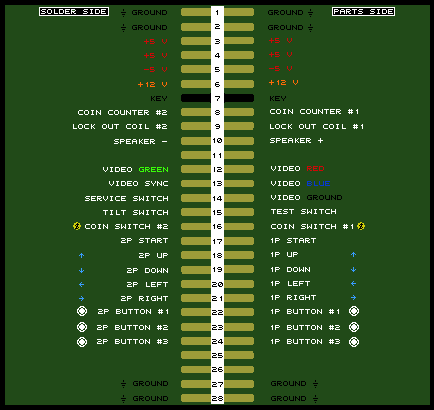
The idea was to run it from the JAMMA connector of my NeoGeo 1-25 to the bottom of the cab, where I have a piece of wood upon which to place other JAMMA boards.

I know that other NeoGeos aren't JAMMA, but that this early model supposedly is.

I've hooked in a JAMMA board straight to the connector of this cab, and it ran beautifully (albeit without sound, a problem for which I know the solution, so no worries there -- I ran my board with a temporary electrical tape setup that did yield noise).

However, when I put the extender harness onto the cab's connector and the MV-1 motherboard, I get no sound (which is weird since the sound comes from a completely separate molex thing), and none of the buttons seem to work. EDIT: This "no sound or buttons" problem occurs on both my TMNT board and my MV-1 board.

My guess is that the extender jammaboards.com sells is for JAMMA, but for JAMMA which connects different wires than those used by the 1-25.

I just want it to work, and I'm not afraid of soldering if necessary.

What can I do to turn that extender I linked into something that will let me extend out to other JAMMA boards in my Neo 1-25 cab?

If any further information is necessary, just ask.

Off-topic question: I'll make a separate thread for if no one has an answer: Is there a way to turn down the volume on a Teenage Mutant Ninja Turtles board? When I tested my sound solution earlier, it damn near launched my cab into space from sheer force of speaker usage power.

EDIT: Off-Topic Answer: found the potentiometer. Much more reasonable sound level now.
 
Last edited:

Murray

Akari's Big Brother
Joined
Aug 16, 2005
Posts
2,533
I don't know how much this helps (it's 4am), but I got one of those extenders and also had problems. I didn't bother to fix it but I'm pretty sure there are just some pins that aren't connected.

It shouldn't matter what the pinout is. If the extender was properly 1:1 wired, you could hook anything you wanted up to it.
 

ttooddddyy

PNG FTW,
Joined
Nov 29, 2001
Posts
8,335
Remember that jamma is mono and the Mv-1 is mvs stereo. Not sure how your speakers are wired ? jamma or mvs.

Try switching to mono on the board. The speaker(s) should connect between jamma pins L and 10 for mono sound.
 
Joined
Dec 21, 2009
Posts
12
The Jammaboards.com harnesses and extenders are of notoriously poor quality. I've known several other people to have problems with them - from switches not working to ghosting in the video.

Time to break out the pinouts and a multimeter, and find where the breaks in the wiring are.

If you want *good* quality parts - order from Bob Roberts.

-Ian
 

aclbandit

Another Striker
Joined
Aug 10, 2009
Posts
315
It shouldn't matter what the pinout is. If the extender was properly 1:1 wired, you could hook anything you wanted up to it.

See, that was what I thought. I mean, all it *should* do is put pin 1 to pin 1 elsewhere, pin 2 to the extended pin 2, etc.

Also, thanks for the reply at 4 a.m. :P
 

aclbandit

Another Striker
Joined
Aug 10, 2009
Posts
315
Remember that jamma is mono and the Mv-1 is mvs stereo. Not sure how your speakers are wired ? jamma or mvs.

Try switching to mono on the board. The speaker(s) should connect between jamma pins L and 10 for mono sound.

You're correct that the MV-1 is stereo. However, the sound comes from a separate molex connector on the bottom of the board, NOT the main harness. The main JAMMA harness in the first run 1-25 MVS cabs was actually JAMMA, but the audio pins aren't there at all.

I did try flipping the switch anyway, though, but it was to no avail. Even if that had fixed the audio (didn't), that still doesn't quite explain the oddness that is nonfunctional control panel...?
 
Last edited:

aclbandit

Another Striker
Joined
Aug 10, 2009
Posts
315
The Jammaboards.com harnesses and extenders are of notoriously poor quality. I've known several other people to have problems with them - from switches not working to ghosting in the video.

Time to break out the pinouts and a multimeter, and find where the breaks in the wiring are.

If you want *good* quality parts - order from Bob Roberts.

-Ian

I didn't actually find out that Bob Roberts made JAMMA extenders until last night when I was searching for help with mine. I saw a post on this board about it, and was like "damn. Should have gotten one of his."

I don't actually have a multimeter (really should prolly invest in one), but I'm thinking of just desoldering all of the wires on the fingerboard and running all of them again, to the correct spot.

While re-doing the whole extender would certainly solve the problem, I was really hoping that someone had bought one of these and fixed it, and could tell me something like "oh, just put pin 8 on pin 14" or some similar, simple advice.

*shrug*. Absolute worst case I buy from Bob.
 

MKL

Basara's Blade Keeper
20 Year Member
Joined
Mar 8, 2002
Posts
3,686
JAMMA_EXTENDER_HARNESS_WM_584x480.jpg


As can be seen from this pic, the parts side of the fingerboard doesn't have wiring for +5v, -5V and 12V (they're only on solder side). A fingerboard is not like the edge of a jamma board where the VCC contacts on parts side are connected to those of solder side so that even if you have a single +12V wire it will be connected to the contact of both sides. This means that if the harness of your cab has +12V from the PSU connected only to parts side, it won't make it to the board as the extension has +12V wired only on solder side of the fingerboard. And without +12V you can't get sound. Just add a +12V wire to parts side of the fingerboard.

Jammaboards should be ashamed to sell such a piece of crap.
 

aclbandit

Another Striker
Joined
Aug 10, 2009
Posts
315
JAMMA_EXTENDER_HARNESS_WM_584x480.jpg


As can be seen from this pic, the parts side of the fingerboard doesn't have wiring for +5v, -5V and 12V (they're only on solder side). A fingerboard is not like the edge of a jamma board where the VCC contacts on parts side are connected to those of solder side so that even if you have a single +12V wire it will be connected to the contact of both sides. This means that if the harness of your cab has +12V from the PSU connected only to parts side, it won't make it to the board as the extension has +12V wired only on solder side of the fingerboard. And without +12V you can't get sound. Just add a +12V wire to parts side of the fingerboard.

Jammaboards should be ashamed to sell such a piece of crap.

Awesome, just adding wires is much preferred to re-running the whole thing.

Now, that covers sound. Will adding the voltage wires correctly also fix the lack of control panel, or is that something entirely different :(?
 

Xian Xi

JammaNationX,
15 Year Member
Joined
Dec 1, 2005
Posts
27,762
JAMMA_EXTENDER_HARNESS_WM_584x480.jpg


As can be seen from this pic, the parts side of the fingerboard doesn't have wiring for +5v, -5V and 12V (they're only on solder side). A fingerboard is not like the edge of a jamma board where the VCC contacts on parts side are connected to those of solder side so that even if you have a single +12V wire it will be connected to the contact of both sides. This means that if the harness of your cab has +12V from the PSU connected only to parts side, it won't make it to the board as the extension has +12V wired only on solder side of the fingerboard. And without +12V you can't get sound. Just add a +12V wire to parts side of the fingerboard.

Jammaboards should be ashamed to sell such a piece of crap.

That's what I saw as well.

Also if this isn't the problem the only other thing I can think of is possibly a failing PSU. Check your voltage on the +12v line with the extender and PCB hooked up.
 

Xian Xi

JammaNationX,
15 Year Member
Joined
Dec 1, 2005
Posts
27,762
Now, that covers sound. Will adding the voltage wires correctly also fix the lack of control panel, or is that something entirely different :(?

For the controls, check to see if the last 4 ground wires are hooked up on the extender. I can't tell from the pic if they are but if they are missing and your cab uses those specific pins for CP ground then you need to add them or use another ground point.
 

aclbandit

Another Striker
Joined
Aug 10, 2009
Posts
315
That's what I saw as well.

Also if this isn't the problem the only other thing I can think of is possibly a failing PSU. Check your voltage on the +12v line with the extender and PCB hooked up.

Okay, I'll look at the voltage lines. I also SERIOUSLY doubt it's a failing PSU, since it was (a few months ago) a brand-new one from HAPP controls. Also, hooking either the MV-1 board or the TMNT board straight into the 1-25 MVS's harness works perfectly, so it's probably only a problem with this extender and nothing in my cab.

For the controls, check to see if the last 4 ground wires are hooked up on the extender. I can't tell from the pic if they are but if they are missing and your cab uses those specific pins for CP ground then you need to add them or use another ground point.

If by "last four" you mean pins 27 & 28 on both sides, then... um... well, it has pin 28 hooked in on both sides >_<;;

Just to be sure we're all on the same page as far as pins & numbering, I'm using this image for reference:
jamma_pinout.gif
 

aclbandit

Another Striker
Joined
Aug 10, 2009
Posts
315
So, for the +12v line that's only on one side, can I just run a wire from the soldering point on the one side to the other, or do I need to "move" the line to the other side?

EDIT: Also, the -5v being wrong isn't an issue, I don't think, since I'm not running any -5v boards. My MVS cab, I believe, doesn't have a -5v line anyway. I think there's a stickied thread somewhere about -5v stuff, and IIRC, it's a very short list... right?
 

Xian Xi

JammaNationX,
15 Year Member
Joined
Dec 1, 2005
Posts
27,762
Ya, you can run a line from one side to the other try to match the gauge if you can.
 

aclbandit

Another Striker
Joined
Aug 10, 2009
Posts
315
Ya, you can run a line from one side to the other try to match the gauge if you can.

Great. Sound now appears fixed. Gonna do the same type of bridging to the pins 1-2 ground, and run a full line for pin 27 to see if I can't get the CP going too.
 

aclbandit

Another Striker
Joined
Aug 10, 2009
Posts
315
All ground is now properly wired, but I still have no control panel (or, at least no start button -- can't very well test the other buttons if I can't start the game).

Advice?
 

MKL

Basara's Blade Keeper
20 Year Member
Joined
Mar 8, 2002
Posts
3,686
Will adding the voltage wires correctly also fix the lack of control panel, or is that something entirely different :(?

I missed the CP issue. No, that must have to do with lack of grounding. I don't know what cab you have but if it were an Egret II or an AWSD that's what you would be experiencing because those cabs use the ground contacts at the other end of the jamma connector as follows:

27 = coin switch
e = control panel (P1 and P2)
28 = service and test switches
f = not connected

Now, that jamma extension only has pins 28 and f wired, which would explain why the controls don't work.

Even if your cab isn't an Egret/AWSD it could be wired the same in this respect.
Again, the solution is adding wires...
 

aclbandit

Another Striker
Joined
Aug 10, 2009
Posts
315
Aha. Player 2's start button works, but player 1's does not. After starting, all of the P2 controls work fine.

So. Let's get P1 going.

EDIT: Got it! Redid the solder on both ends. Guess someone got lazy.

DONE :)
 
Last edited:

aclbandit

Another Striker
Joined
Aug 10, 2009
Posts
315
So, the list of things one must do to this (at least as far as I can tell) is as follows:

1) wire the parts side +5v and the solder side +5v together on the fingerboard end
2) wire the parts side +12v and the solder side +12v together on the fingerboard end

3) (Optional... probably) If you need it, wire the -5v similarly.

4) run pin 27 to pin 27 on both the parts and solder side, respectively, since this wire is missing altogether and may be necessary.

6) Try it out, and fix any wires that have craptastic soldering jobs.

This list is here in case some other poor misguided soul happens to wind up with one of these poorly-made, craptastic extenders.

If you're looking for my advice... go with the one from BobRoberts. So there.

EDIT: Step 5 has been removed. It seemed to cause some odd issues. ???
 
Last edited:

aclbandit

Another Striker
Joined
Aug 10, 2009
Posts
315
Well... actually... something IS wrong.

The TMNT board is just constantly resetting. I have no idea why.

Halp?
 

aclbandit

Another Striker
Joined
Aug 10, 2009
Posts
315
Well... actually... something IS wrong.

The TMNT board is just constantly resetting. I have no idea why.

Halp?

Apparently if the negative lead on the speaker isn't making good connection (but the positive is), it resets. Whoops.

The reason the MVS didn't have trouble, of course, is because it doesn't CARE if the speakers are connected or not on the main harness, since its audio goes somewhere else.

I *think* I'm totally done now.

Thanks a lot, guys -- my TMNT board has sound AND controls through the extender harness. :multi_co:
 
Top