Ok, First lets start with some links
Moosmann Website on RGB mod NES
-------------------------------------------------
http://mbrandel.vizionaires.net/?page_id=107
Forum post that talks about doing the RGB mod to your NES
-----------------------------------------------------------------------------
http://nfggames.com/forum2/index.php?topic=1592
(Thanks norton9478)
PPU Information Link ( I used the RC2C03B PPU)
---------------------------------
http://johnsarcade.com/nintendo_vs_ppu_info.php
RGB Color Booster
---------------------------------
http://i16.photobucket.com/albums/b14/moosmann/electronic/famiamp.png
http://i16.photobucket.com/albums/b14/moosmann/electronic/sep015.jpg
Pas already touched on this, but here is a general NES to JAMMA checklist
1. Get a PPU that can output RGB and has similar color palette to NES. I used the RC2C03B PPU as this was recommended by Moosmann. The PPU can be found on Playchoice boards as well as a select set of VS titles (Tennis/ Duck Hunt)
2. Remove old PPU and replace with socket (40 pin I think). You want to use a good quality socket, one with the round holes - precision socket I think
2a. When installing the socket - you need to lift the RGB pins. The PPU outputs un-amplified RGB signals that need to be amplified before displaying on an arcade monitor.
3. Either build an RGB amp or use an ultimarc (Thanks again norton9478). Feed the un-amplified RGB into the amp - out from the amp to the jamma edge connector.
4. The PPU also outputs un-amplified SYNC signal - you can pull the sync from the 'point of picture'. I had the run the Sync through a JROK sync cleaner - otherwise I had wavy lines on the Egret. (Not needed on a Neo Candy 29 - Go figure). Terminate this 'cleaned' sync signal to the jamma edge connector.
--------------------Video Done------------------------------------------------
5. The sound needs to be amplified for arcade speakers. I just ran the sound through a PCB from a set of old PC speakers. The speaker amp needs 12Volt, which I take from the JAMMA edge connector. Still mono, then again, so is the cab so it works for me. Also, now I have a dial to adjust sound volume.
--------------Sound Done---------------------------------------------------
6. I hacked 2 NES pads (They had button problems to begin with

) and wired the hacked pads to the JAMMA edge connector. I used a DPDT switch on the clock and latch signals of the controller to allow me to switch between the hacked pads in the JAMMA NES, and external controller ports. This allows me to hook a light gun up and play duckhunt or some Hogans Alley. Also, if I want to ever use a D-Pad, I can always just hook one up.
...and then you get to deal with the controller interface. I built my own rather than hacking controllers apart because I had more control over size and could keep the controllers for use on my main NES I keep hooked up in the house
Wow building your own controller interface - thats freakin sweet.

---------------------Controller Done----------------------------------------
7. Now we need to power this beast. I hook my NES right off the 12v of the JAMMA edge connector. I know the NES runs on 9volt, but works fine on 12. Also, I hooked up a watt meter and am drawing less than 1.0 amp (.8 actually) off the 12volt, so my PS aint getting abused. Hopefully

-------------------Power Done---------------------------------------------------
Also, for shits I decided to make my old NES a top-loader while I was soldering on it anyways. I had an old project box from a fucked up supergun, so I decided to stick all the guts in that. I did not even this this would work in the begining, so my wire colors are all wrong and the box is a little sloppy, but here it is
--------------------Top-Loader Done-----------------------------------------
Bottom of NES mainboard. You can see the new PPU installed in its socket. Also, you can see the RGB amp mounted upside down. Notice the top-loader connector soldered to the edge connector of the mainboard.
Another shot of the bottom - this one with the hacked pads installed.
Top of Jamma NES. In the bottom left are the RGB pots. These pots are connected to the RGB amp - like my knobs??? Notice the sync cleaner in the top left. Top loader connector show in top center - duh. I removed the RF/PS unit and use a short run of wire to connect it. Relocating this let me stick the NES in a small project box. On the right is where the controller ports will go. Notice the DPDT switches to allow me to switch between the hacked pads below and the controller ports.
Top of Jamma NES with sound amp installed and controller ports installed
Side shot showing switches and controller ports. Notice the solid piece of Maple under the game connector.( Just the very edge shown in the pic) THis is epoxied to the bottom of the connector and I will screw it to the bottom of the box. This provides great compression support and good extraction support.
Opposite side with JAMMA edge connector. Cut a slot and epoxied it in. Used some black dye in the epoxy.
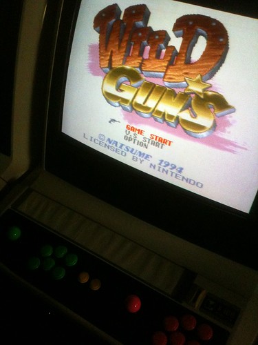
Jamma NES installed in Egret 2. Notice the way the cart faces. This is just how it needs to face with the top-loader mod. All you are basically doing is taking the cart in the orig. position and rotating it up 90 degrees.
More
Like I said, I can use the gun. Not very well though

Yes I took that Dial off. I actually put it on the Egret 2 as the dial for the sound pot. Anything for the Egret 2
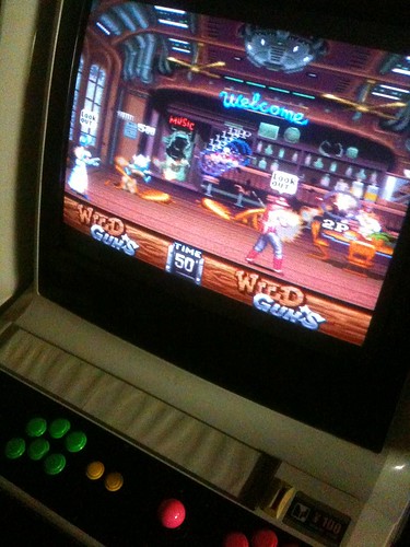
Zelda on a Cab. This is a bad pic, looks much better in person -
One More

") If you want I can always make you a jamma NES, Genesis, TG-16, or PCEngine (Im sure there are others as well but those are the ones I have made so far and am 100% sure I can do) but they arent cheap to build right...hack jobs can be made prity cheap but I dont like to go that route...I like my stuff durrable and built to last forever
If you want I can always make you a jamma NES, Genesis, TG-16, or PCEngine (Im sure there are others as well but those are the ones I have made so far and am 100% sure I can do) but they arent cheap to build right...hack jobs can be made prity cheap but I dont like to go that route...I like my stuff durrable and built to last forever 


")