Consolizing MV-2F

BTD

Armored Scrum Object
Joined
Nov 30, 2008
Posts
248
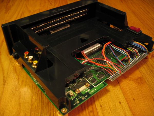
So recently I've decided to consolize an MV-2F board. I chose this for the obvious reasons (controller ports all ready on board, mem card reader etc..) What I'm having trouble finding is a how-to for these boards. I'm not against figuring out these things for my self, as I've done plenty of modding before just never with MVS hardware.

I guess what I'm really asking, is since the controllers are already wired, what do I still have left to do?

Wire in the RGB-NTSC vid converter

Supply it power

Wire in the audio stereo out

EDIT- maybe some pics like this page (it's hard to vizualize all those solder points without any pics)
http://shmups.system11.org/viewtopic.php?t=22235

This is all I can come up with.

These boards are all similar I've found out, but with large enough differences that would render a certain process or step usless or necessary. I imagine this all sounds muddled but I'd appreciate any help from you guys.

Thanks
Tony

EDIT #2- If someone could just take the lid off their 2-slot and take a pic of it wired on top and the bottom of the board, that'd help a ton
 
Last edited:

joe8

Legend of Threadless Joe
15 Year Member
Joined
Oct 25, 2007
Posts
4,329
Does anybody know how to go about adding a transparent perspex base to the 2-slot? Do u have to get a pro to cut the perspex(to get neat edges) or can you do it yourself. Also does anyone have pics for how to wire up a power switch and LED?
 

BTD

Armored Scrum Object
Joined
Nov 30, 2008
Posts
248
Not exactly what I was looking for, lol. But hey- maybe someone can help both of us out :)
 

BTD

Armored Scrum Object
Joined
Nov 30, 2008
Posts
248
Come on guys, I could really use the help!
 

aluisi

Geese's Thug
Joined
Apr 3, 2002
Posts
271
Don't know if this helps you or not

http://www.hardmvs.com/manuals/MV-2FserviceManual.pdf

Seams like your on the right track. all you need to do it get a video converter i would get a Jrok one since you can do all the video out puts under the sun. Don't worry about hooking up the 12v line its only used for the coin counters. Get a good 5v power supply and you should be good to go

All you really are missing is to hook up some external buttons. 1 button on Select up or down it doesn't mater so that way you can select between the two carts. And 2 Buttons one for the Service and Test switch. Don't worry about start or credit buttons. I believe the controller ports you can use the start button on the controller. And make sure you have Dip 7 set to on and the board is in free play mode. Also pop a unibios in that bad boy :)

Hope that helps

Also hook up a power switch. All you need is a 2 pole on / off switch. Run the 5v in from the power supply to the middle pole and then a wire from the first pole to the 5v in on the board. That way you can turn it off with out unplugging it from the wall. As for a reset switch you can use the test or service I cant remember what one to enter the bios and just exit out of it. Or if you do put a unibios in it you can do a soft reset by pressing start A & B (i think) and that takes you into the Unibios menu.
 
Last edited:

BTD

Armored Scrum Object
Joined
Nov 30, 2008
Posts
248
Thanks for the info. :) I was looking at that pinout from the manual as I checked back over here. With a unibios though, I wouldn't have to wire extra buttons correct? I don't want to have any extras hanging off I don't really need.
 

aluisi

Geese's Thug
Joined
Apr 3, 2002
Posts
271
Thanks for the info. :) I was looking at that pinout from the manual as I checked back over here. With a unibios though, I wouldn't have to wire extra buttons correct? I don't want to have any extras hanging off I don't really need.

No you dont have to have any extra buttons with the UniBios. I updated my otehr post about it. You do need to have 3 buttons though as I mentioned above. 1 button hook to select up or down on the board it doesnt mater what one. And then 2 more buttons for Test and Service. You need all three buttons hooked up.
 

aluisi

Geese's Thug
Joined
Apr 3, 2002
Posts
271
Shit you might just need 2 buttons one for selecting the game and 1 for the service or is it the test to get in to the boards menu. Some one correct me here if I am wrong.

The UniBios is controlled by the controller. Hitting start and the Select (the one for selecting a cart) pauses the game. hitting A,B and Start on your controller gets you into the Cheat menu
 
Last edited:

BTD

Armored Scrum Object
Joined
Nov 30, 2008
Posts
248
OK- so this is the route I think i'm going: NOTE- I want a dedicated Board- not interested in Jamma Harness

2 Slot (I have already)

A standard wall power supply as mentioned in http://www.neo-geo.com/wiki/index.php?title=How_to_Consolize_an_MVS_Board

RGB-NTSC (I understand the pinouts)

UniBios

some random jacks

tools, solder, wires, etc.

I THINK this will be it. I'm still a little lost on where to mount the vid outs/connect them. I would kill for some pics of a dedicated consolized MVS board

And thank you sir, you have been very helpful :)
 

BTD

Armored Scrum Object
Joined
Nov 30, 2008
Posts
248
Yeah, it did give me a better overall mental picture. Thank you. What I'm really looking for is for someone just to take the top off of theirs so I can see the insides. That would be great. Thanks for the help Koopa.
 

aluisi

Geese's Thug
Joined
Apr 3, 2002
Posts
271
Found this pic on ebay :p

NEO2SLOT.jpg


You have a butt load of space to work with. You can mount anything any where. Just make sure when you do your video encoder to put something on the bottom of it so no contacts touch the Neo board. Also you don't need a jamma harness to do this, solder the wire directly to the jamma connector on the board.
 
Last edited:

BTD

Armored Scrum Object
Joined
Nov 30, 2008
Posts
248
Yeah, I was planning on soldering right to the pins. I have a 2 slot board (got a little excited too quickly) and I've done a lot of staring at it. I was really looking for a wired board I could take a peek at.
 

Koopa64

Sieger's Squire
Joined
Dec 11, 2008
Posts
820
Yeah, it did give me a better overall mental picture. Thank you. What I'm really looking for is for someone just to take the top off of theirs so I can see the insides. That would be great. Thanks for the help Koopa.

Yeah I was afraid of that, I don't think I've come across any pics of a naked 2-Slot CMVS before, perhaps you could ask for someone to do that for you here?
 

BTD

Armored Scrum Object
Joined
Nov 30, 2008
Posts
248
Good idea. So does anyone have a naked CMVS I could get a few pics of? That'd be great if you did :)
 

BTD

Armored Scrum Object
Joined
Nov 30, 2008
Posts
248
Yes, actually that helps a ton. I'm assuming the bundle of wires to the right of the jamma board are going under the board to the solder-side board pins?
 

norton9478

So Many Posts
No Time
For Games.
20 Year Member
Joined
Oct 30, 2003
Posts
34,075
Don't solder to the Pins unless you wanna be laughed at.....

Get a Multimeter and find other points to solder too.
top.jpg

CMVS01.jpg

Dscf0070.jpg


Also, get your audio from teh headphone output... It is cleaner than getting it off the jamma edge and attenuating it.
 
Last edited:

BTD

Armored Scrum Object
Joined
Nov 30, 2008
Posts
248
Well the only person that'd be laughing would be me. Even still, it'd be nice to stay away from the Jamma pins. There again though- I wouldn't know how to find the right points on the board.
 

norton9478

So Many Posts
No Time
For Games.
20 Year Member
Joined
Oct 30, 2003
Posts
34,075
Well the only person that'd be laughing would be me. Even still, it'd be nice to stay away from the Jamma pins. There again though- I wouldn't know how to find the right points on the board.

Do you have a Multimeter with continuity test?
 

Xian Xi

JammaNationX,
15 Year Member
Joined
Dec 1, 2005
Posts
27,762
Trace the pins back. Put one lead on the jamma pin and visually follow the trace to somewhere under the shell and to make sure it's the right one put the other lead on it and it should beep.

It's really simple. A 2 slot can be consolized in 3 hours time, only took me 2 hours with painting.
 

BTD

Armored Scrum Object
Joined
Nov 30, 2008
Posts
248
Trace the pins back. Put one lead on the jamma pin and visually follow the trace to somewhere under the shell and to make sure it's the right one put the other lead on it and it should beep.

It's really simple. A 2 slot can be consolized in 3 hours time, only took me 2 hours with painting.

That actually makes a ton of sense. I'm still a little shifty on some ideas (pulling stereo off the headphone jacks) but i think I just may be able to help. Thanks a ton for all the help fellas. And by all means, keep the suggestions coming.
 

Xian Xi

JammaNationX,
15 Year Member
Joined
Dec 1, 2005
Posts
27,762
Do the +5v only mod as well. You have to bridge some connections on the audio and remove some caps for it to work.
 
Top