Need a little console to jamma help here plz plz plz

aluisi

Geese's Thug
Joined
Apr 3, 2002
Posts
271
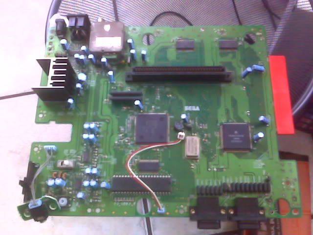
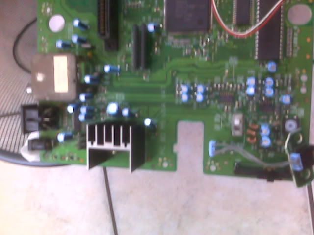
So I found a guide to turing genesis and snes etc... to jamma. So I thought I would start with the easy one first the Genesis. I have the main idea and all the tools and I am almost done i just have a few issues I need help with. I know the genesis runs 9V 850mA. So I want to pull the power for the system from the jamma harness. I want to pull from the 12v on the jamma to power the genesis. I asume I need a resistor to drop the power from 12v to 9v. What kinda resistor do you all recommend and is this the right thing to do? The other issue I am dealing with is the sound. I want to pull the sound from the front headphone jack onto the jamma. There are 3 wires connecting the jack to the genesis. So does any one know the pin outs for these three wires? As in what one is the Left, Right and Ground for the headphone jack?

Thanks in advance. I am almost done all I need is to figure out these issues and I am done. And before any one asks me to to make them one I have no plans to make any more. It's a pain in the ass to get as far as I did and I am just making this for myself.

aluisi
 

aluisi

Geese's Thug
Joined
Apr 3, 2002
Posts
271
come on some one on here has to have done this before and can help me out. I am almost done
 

Hewitson

Metal Slug Mechanic
Joined
Mar 6, 2008
Posts
2,198
The Megadrive/Genesis has a regulator on the PCB as its power supply is unregulated. However 12v would probably over heat it too much.

To work out the resistor needed we need to know how many amps your power supply outputs on the 12v line.
 

Murray

Akari's Big Brother
Joined
Aug 16, 2005
Posts
2,533
I just finished doing this to a model 1.

First, do you intend to continue using the Genesis as a Genesis?

If you don't, this is easy. The Genesis actually runs on 5V. There are two voltage regulators connected to a big heat sink on the board that convert the 9V to 5V. Remove them both and connect the 5V lines from the JAMMA harness to where their outputs were, and ground to where their ground connections were.

You can't just run RGB and sync to the harness. RGB need to run through 220uF caps (one cap for each line). For sync, you either need to buffer the signal or use composite video with an LM1881 to get a stable sync signal. The quality of the video will be better if you pull it straight off the video encoder chip, rather than the AV jack.

You will need to amplify the sound coming from the Genesis. Of course it's stereo so you'll need to decide whether you want to use the stereo or downmix to mono (or if it's a Genesis 1, you can just amplify the mono coming from the AV jack). I just used the amp yanked out of some small PC speakers for this. The PC speaker amp runs on 12V in my case, so powering it from the edge connector was feasible.

Finally, you will have to consider the controllers. I just used some old controllers I had lying around and wired the directions / buttons to them, then soldered them to the Genesis board. If you really want yours to be clean, the best way would be to get the multiplexer off the board and build your own circuit (but smaller).

Edit: There are some useful pinouts here.
 

aluisi

Geese's Thug
Joined
Apr 3, 2002
Posts
271
I dont plan on using the genesis as a genesis any more. i want to use it specificly for jamma. Thanks a bunch for your help. On my modle 1 might be a diferant. This is the version I am using

IMG00152.jpg

IMG00154.jpg


so is there any speific thing I need to do to get the power working and the video? Also i dont have to amp the sound do I if I take it directly from the stero jack?
 

Drewmantrivia

Crazed MVS Addict
Joined
Apr 4, 2005
Posts
136
Just a thought but you may want to wire up a external power and reset switch while your at it. Make life easier i would thing. Just a thought.
 

Murray

Akari's Big Brother
Joined
Aug 16, 2005
Posts
2,533
Yes, yours is a bit different. It looks like the last version of the model 1 (practically a model 2).

On the side of the board, look at the component(s) connected to that big heat sink. There will be one or more voltage regulators (7805 = 5V). That's where you want to connect the power.

You will still have to amp the sound coming from the stereo jack. In fact, with this model, you may want to completely rebuild the audio mixing circuit (if you have the patience). This thread on Sega-16.com will be helpful with that if you want to check into it.
 

aluisi

Geese's Thug
Joined
Apr 3, 2002
Posts
271
YA its a VA7 the last model 1 version. There is only one voltage regulator on there. So I should take out the heat sink as well as the voltage regulator. Now where exactly do i hook up the 5v? there are 3 spots on the board they are O G I
G i assume is the ground. So how do i get directly into this. Also i am redoing the video now after what you said. I have the small 24pin SOP encoder chip on my genesis. It will take some time to get the solder points just right. i am looking into the amp thread. Thanks again for your help. I guess if I had a first gen model 1 this would be easier lol
 

Murray

Akari's Big Brother
Joined
Aug 16, 2005
Posts
2,533
The heat sink is there just for the voltage regulator so if you remove the regulator, you can remove the heat sink. If I had to guess, I'd say O is out (connect your 5V here), G is ground (connect that to ground on the edge connector), and I is in (ignore this). However, I'd recommend looking up a data sheet for the specific regulator that's on there to make sure.

Aside from the audio mixing circuit, I don't think an older model would be much easier. I had to build everything on mine at least 3x. Once like I thought it should be, once trying to make it better, and once getting it right. :)
 

aluisi

Geese's Thug
Joined
Apr 3, 2002
Posts
271
Okay i will look up my specific board. That sound mod is quite the involved process. I am going to do it though. So with the video on the 220uF caps does it make a difference in the way its hooked? I have read some people saying the negative of the cap should be on the monitor side etc. I wouldn't think it would be to much of a difference. Also the LM1881 comp. sync i am having a bitch of a time finding this chip. also how is this supposed to be hooked up? Do you just hook up power and ground and comp in comp sync out?
 

Murray

Akari's Big Brother
Joined
Aug 16, 2005
Posts
2,533
I have my video lines connected like in this diagram. Yes, the polarity matters on the caps (negative should be on the monitor side). Also, without the caps, I was completely unable to get the video to display.

As for the LM1881, I went by this info. Digi-key has them, though only in the SOIC form factor. Newark claims to have the DIP variant. It's a very simple circuit. You should be able to find the caps it needs at Radio Shack but that 680Kohm resistor should probably be ordered with your IC.
 

aluisi

Geese's Thug
Joined
Apr 3, 2002
Posts
271
Okay stupid question incoming....... The info on hooking up the LM1881

lm1881.gif


From what I read you don't need to worry about pins 3, 7 & 5. The composite Video input I hook the comp. sync into that pin (pin 2) correct? and dumb question here whats the 0.1uf for on this pin. I am kinda new to this stuff. If its replacing a chip and stuff like that just swapping things its no problem for me lol. Okay pin 8 I can hook either 5 or 12v from the jamma to that pin right? Pin 1 the sync out goes to the video sync on the jamma right? Now what do I hook up pin 6 to? The one that needs the resistor? and that's with the I assume jumper wire here with the 0.1uf for.

thanks again!!
 

Murray

Akari's Big Brother
Joined
Aug 16, 2005
Posts
2,533
Correct on 3, 7, & 5.

I'm not exactly sure what the caps on 2 and 6 do. I can follow a diagram but don't really know the theory. :)

Correct on 8, but you should have enough 5V to go around. Just connect it to that.

Correct on pin 1.

Pin 6 is just what it looks like. You connect it to a 0.1uF cap and 680Kohm resistor, in parallel, to ground. Again, I'm not clear on what it's actually doing, but that's what the diagram says and that's what worked for me. Basically, it's like this:

Code:
    |---0.1uF---|
6 --|           +-- ground
    |--680Kohm--|

... and 4 goes straight to ground.

Does that clear it up? :)
 

aluisi

Geese's Thug
Joined
Apr 3, 2002
Posts
271
one last thing. Pin 2. I hook up the comp. sync into that pin right?

Also is it feasibly to use a Sega CD with this? Since the Sega CD runs off of 9v is there a way to mod the CD unit to accept the power from the jamma harness in the same way? I know the back of the original CD unit only has power L / R audio and some type of mixer input/output thing. Also is there any sound changes I have to do with the CD unit its self or just use the existing sound from the genesis.

Ohhh one more thing do you recommend amping the audio with a sound amp from the AV jack or using the clear sound mod and running it from the headphone jack? Does any one know about these amps and if there any good? http://www.itcelectronics.com/product_info.php?products_id=1639

ohhhh ya i forgot can you use the existing power switch and reset switch while its hook into the jamma and the cab is on or do you have to mod one in there specifically and how do you do that lol
 
Last edited:

Murray

Akari's Big Brother
Joined
Aug 16, 2005
Posts
2,533
You connect the composite video signal to pin 2, not sync.

In theory, you could run a Sega CD with this but I haven't been inside one recently to know if you could run it from 5V. I didn't even try with mine because I was mostly doing it for Streets of Rage 2. :) Read in that thread about the crystal clear mod to see if they've come up with a way to make it work with the Sega CD.

You're going to have to amp the sound whether it's coming from the AV jack or the headphone jack. Using the crystal clear mod will completely disable the mono audio coming from the AV jack, though. If you want to use mono sound, you should not use the crystal clear audio mod.

I've built a couple of Velleman kits (though not that one) and they work well enough. It doesn't take much to run arcade cabinet speakers. If you want stereo audio, you will need two of that kit, though.

Unless you intentionally remove them, your power and reset switches will continue to work as they always did.
 

aluisi

Geese's Thug
Joined
Apr 3, 2002
Posts
271
okay everything i need now is on its way. I just need to pick up another genesis controller and I am putting it all together. Thanks a bunch Murray for all your help. I might hit ya up again if I am having issues and I will post pics of it when its all done.
 

Murray

Akari's Big Brother
Joined
Aug 16, 2005
Posts
2,533
Cool. No problem if you need more help. I'd like to see the pics if you feel like posting them.

I may post pics of mine, but it's not a pretty sight. Lots of electrical tape all over the place but it gets the job done. :)
 

aluisi

Geese's Thug
Joined
Apr 3, 2002
Posts
271
I would love to see pics of yours inside and out. It would give me a great idea of where to place things. I should be getting all my parts next week. So I will post in progress pics and completed (crosses fingers) running pics
 

norton9478

So Many Posts
No Time
For Games.
20 Year Member
Joined
Oct 30, 2003
Posts
34,074
Why can't you just take the Sync input off the Encoder chip???

Always seemed to work for me.
 

Murray

Akari's Big Brother
Joined
Aug 16, 2005
Posts
2,533
Why can't you just take the Sync input off the Encoder chip???

Always seemed to work for me.
It completely didn't work for me. It might have something to do with the monitor, but the one on my MVS-U4 didn't like it at all. Straight off the encoder, I couldn't get any kind of usable video. Running it through a cap (like the RGB lines), it was usable, but had ghosting and a weird wavy vertical bar down the middle.

Apparently the sync needs to be buffered to be completely stable. The two ways to do that are running it through a non-inverting logic gate or getting sync from the composite video. Here's the thread on Sega-16.com where I got help straightening this out.
 

norton9478

So Many Posts
No Time
For Games.
20 Year Member
Joined
Oct 30, 2003
Posts
34,074
It completely didn't work for me. It might have something to do with the monitor, but the one on my MVS-U4 didn't like it at all. Straight off the encoder, I couldn't get any kind of usable video. Running it through a cap (like the RGB lines), it was usable, but had ghosting and a weird wavy vertical bar down the middle.

Apparently the sync needs to be buffered to be completely stable. The two ways to do that are running it through a non-inverting logic gate or getting sync from the composite video. Here's the thread on Sega-16.com where I got help straightening this out.

Did you use the Sync input or output?

I used the Input on that encoder chip...
It worked fine on my electrohome... G08
 

Murray

Akari's Big Brother
Joined
Aug 16, 2005
Posts
2,533
Did you use the Sync input or output?

I used the Input on that encoder chip...
It worked fine on my electrohome... G08
Tried sync out from the AV jack and sync out from the CXA1145. Both had the same problem, but it was a tiny bit cleaner coming straight from the video encoder.

My monitor is whatever's standard in a MVS-U4 25.
 

norton9478

So Many Posts
No Time
For Games.
20 Year Member
Joined
Oct 30, 2003
Posts
34,074
Tried sync out from the AV jack and sync out from the CXA1145. Both had the same problem, but it was a tiny bit cleaner coming straight from the video encoder.

My monitor is whatever's standard in a MVS-U4 25.

Sync out of a cxa or clone is ass....
Try the sync in (Pin 10).

You might even want to cut the trace to the chip...
 
Last edited:

aluisi

Geese's Thug
Joined
Apr 3, 2002
Posts
271
okay since I want to do the video right like you suggested Murray I picked up a 1st gen Genesis. Its has the two voltage regulators on there. Each one is marked 1 3 2. Where do I bring in the 5v connection on the board. I have a feeling the 3 is the ground. So what one do i connect the power to the 1 or the 2?

thanks
 

norton9478

So Many Posts
No Time
For Games.
20 Year Member
Joined
Oct 30, 2003
Posts
34,074
okay since I want to do the video right like you suggested Murray I picked up a 1st gen Genesis. Its has the two voltage regulators on there. Each one is marked 1 3 2. Where do I bring in the 5v connection on the board. I have a feeling the 3 is the ground. So what one do i connect the power to the 1 or the 2?

thanks

Just check with a multimeter.
 
Top